Now we can start creating our schematic.
#Hierarchical sheets
Because we are creating a split, we essentially want to have the same circuitry for both sides, but not the same layout. We can achieve this by using hierarchical sheets. This way the circuitry we make will be duplicated.
#Create the left sheet
-
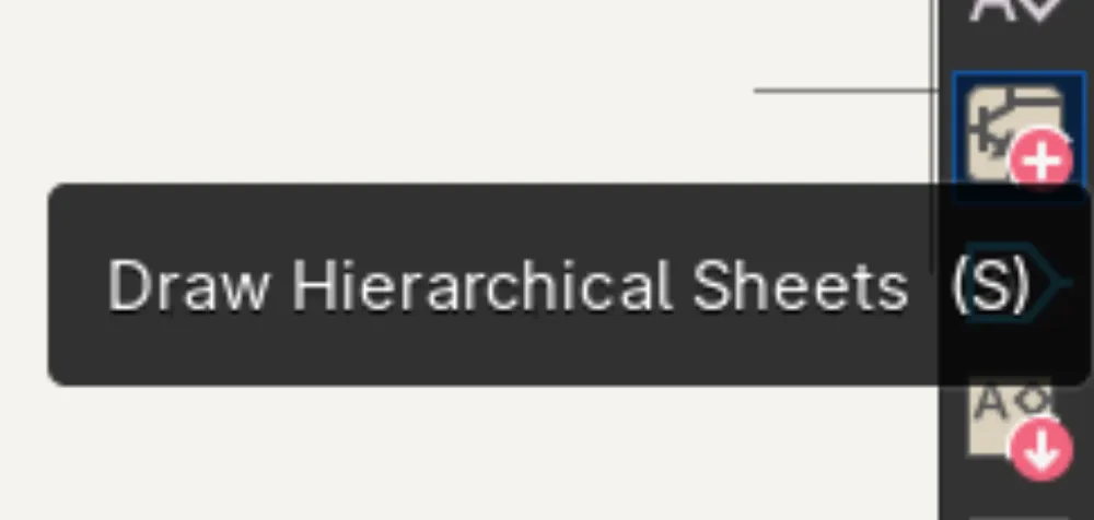
To create a hierarchical sheet, click on this icon on the right sidebar or press S
-
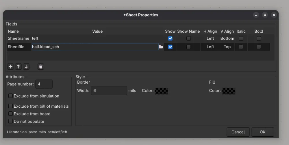
Now draw a rectangle and left-click; a popup should appear:
-
Change the
Sheetnametoleft, and theSheetfiletoside.kicad_sch, and click ok.
#Create the right sheet
-
Now create another sheet, set
Sheetfiletoside.kicad_sch, but theSheetnametoright.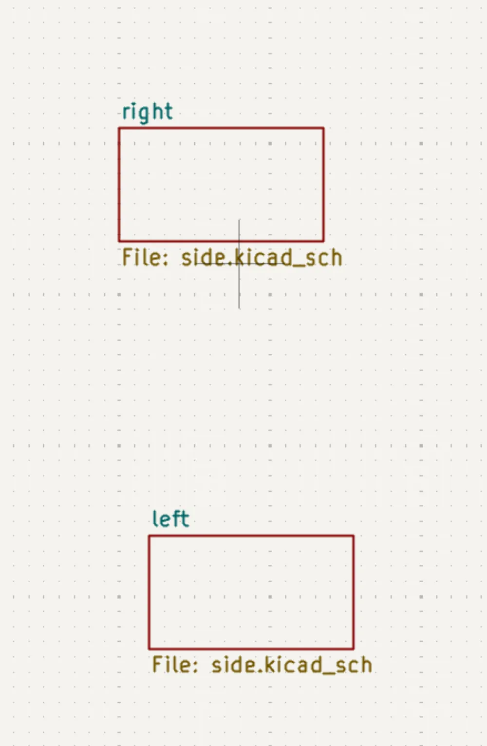
-
And your left sidebar something like this:
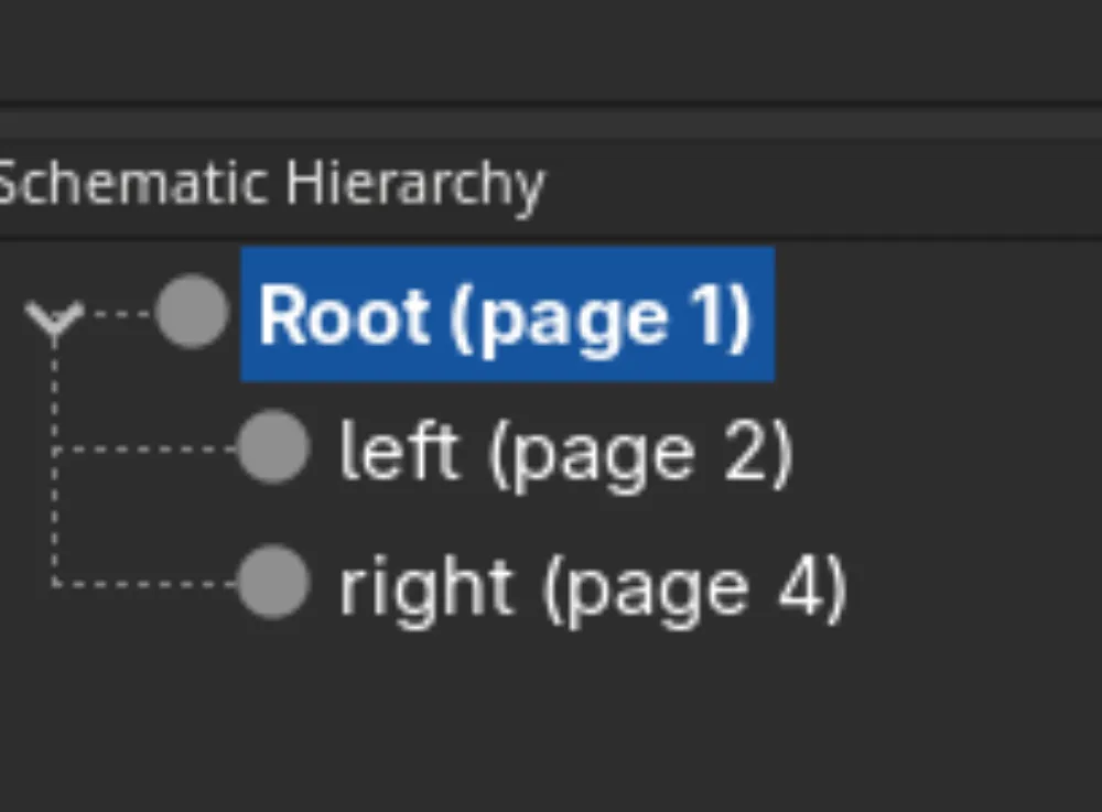
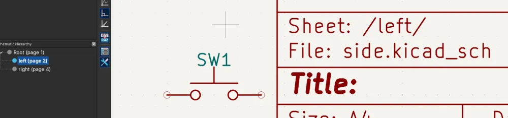
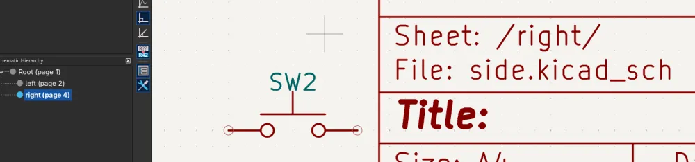
You can now double-click on one of the sheet rectangles in the root sheet or in the left sidebar. You can now place down a switch, for example, and navigate to the other sub/child sheet. You will notice that the switch that you placed down in the other sub-sheet is also in this sub-sheet.
#Circuitry
Now finally we can start to design our keyboard!!!
#Add the XIAO
-
Add the
XIAO-nRF52840-SMDsymbol: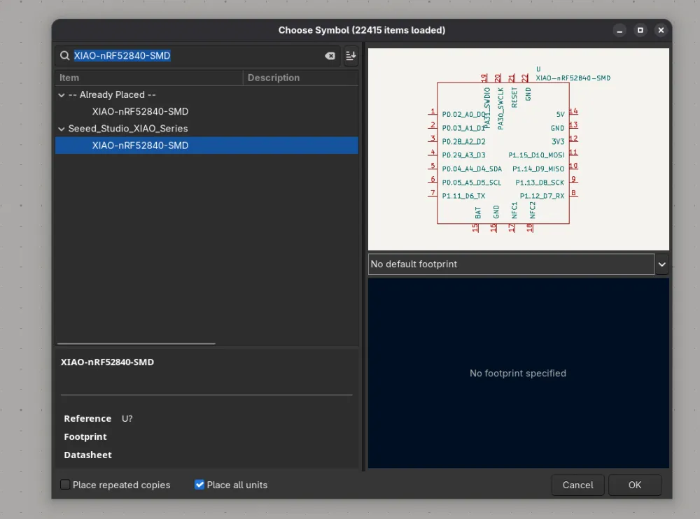
#Add a switch and diode
-
Add a switch
SW_Push: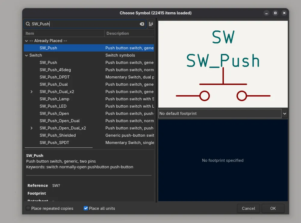
-
And a diode
D(you will see later why we need this):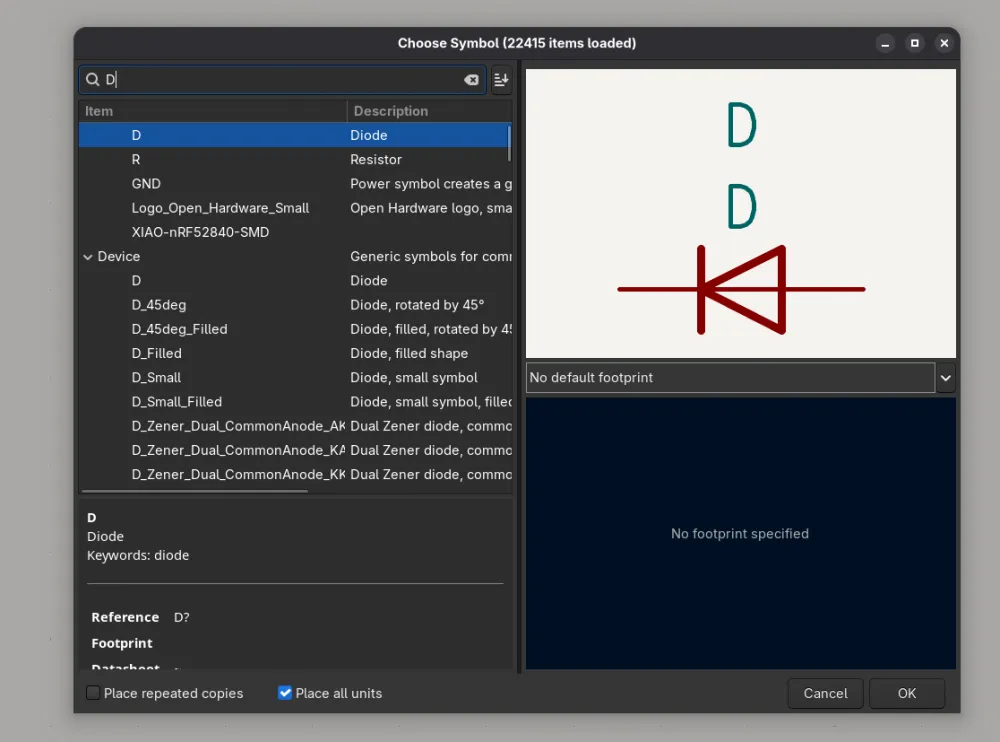
#Keyboard matrix
You may be wondering, why did we need to place down a diode???? You may also notice that the Xiao doesn't have enough pins for a full half of a split keyboard. In comes the humble keyboard matrix; with it we only have to connect one pin per column and one pin per row, drastically reducing the number of pins needed for a keyboard.
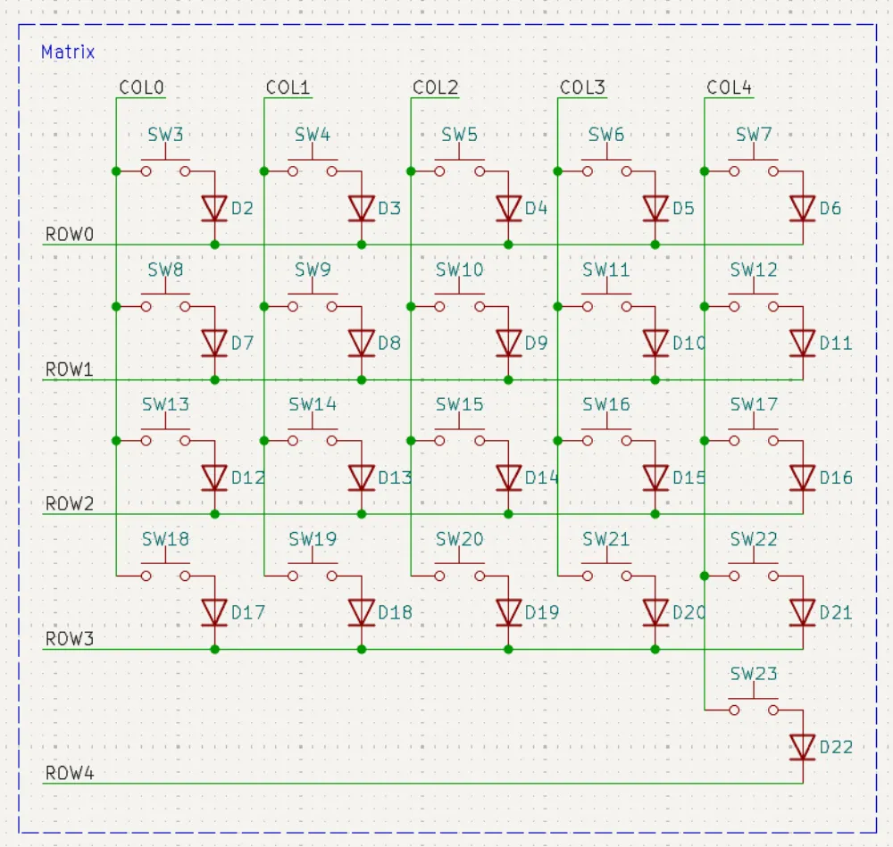
The matrix works by giving power to each column one at a time and checking which keys are pressed down in that row. The matrix will represent our final keyboard layout on our PCB, in this example if we have 4 rows and 5 columns, and one lonely thumb button in the 5th column and the 5th row, in our matrix in the schematic. We will have the same layout of switches on our PCB. We need diodes to prevent ghosting, whereby pressing down one key, the keyboard detects more than one keypress. If you want you can read into keyboard matrixes here.
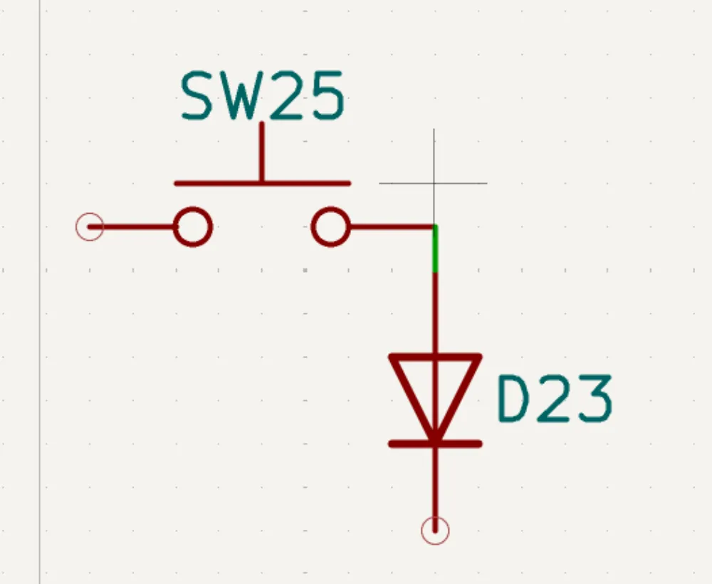
For now all you need to know is that every key has its own diode; this is like one unit:
#Build the matrix
-
You can now make a matrix out of these units; you have to connect the switches to the columns and the diodes to the rows. In this example, in one row I only have one button, which is for my thumb:
#Add labels for rows and columns
-
You may notice that there are labels, like
COL0,COL1, etc., andROW0andROW1. These are labels. You can place these using the L shortcut or from the right sidebar. We can use labels to clean up our schematic. Instead of routing from our Xiao to the column, we just place a label with the same name at the column and one at the Xiao's pin: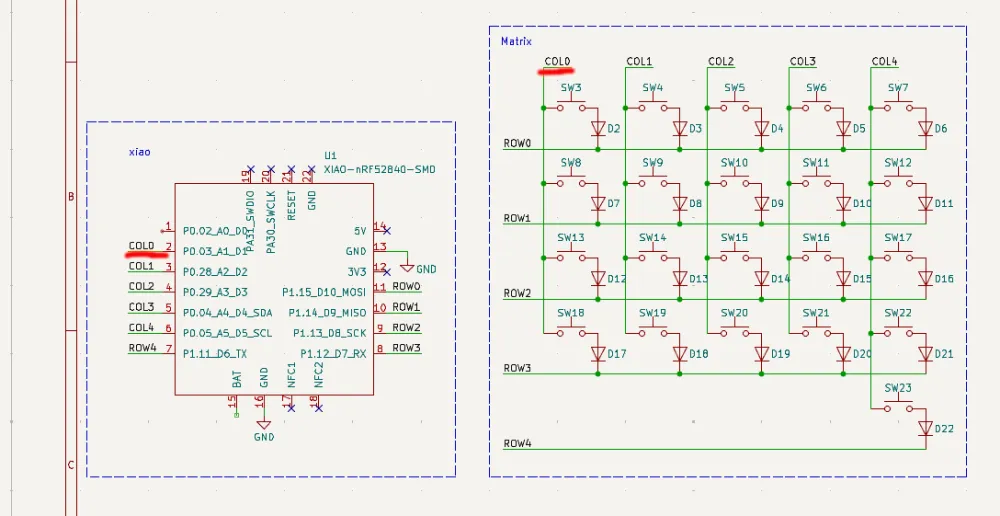
#Battery
Adding a battery is really easy because the Xiao already has battery management built in. We need to add two pads where the battery can be connected to the PCB.
#Add test points and VBAT
-
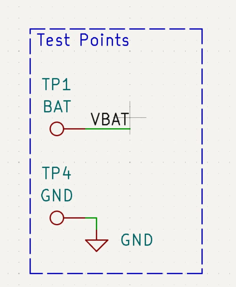
In this case I used two test points, one for the negative side of the battery (aka ground) and one for the live side (aka vbat):
-
And then connect the pin
VBATto theBATpin of the Xiao: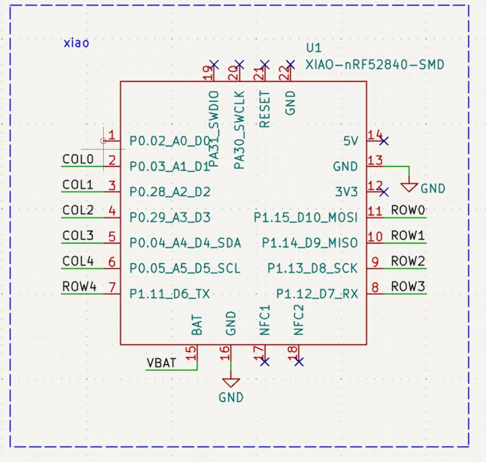
#Sensing the battery voltage
This is an optional feature that lets you see from your computer how much juice is left in your keyboards.
#Add a voltage divider
-
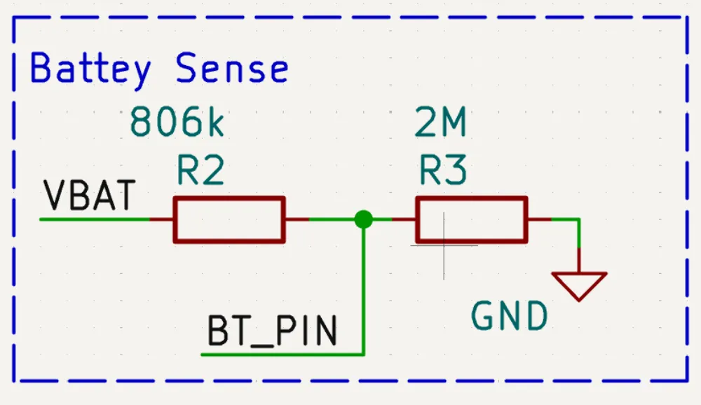
We can achieve this by using a voltage divider, basically two resistors that divide the battery voltage by an amount, so we can measure it with our Xiao. It looks like this. Make sure to use these values for the resistors:
-
And then add the corresponding label (
BT_PINin our case) to the Xiao; make sure that it is an analog pin (has A* at the end):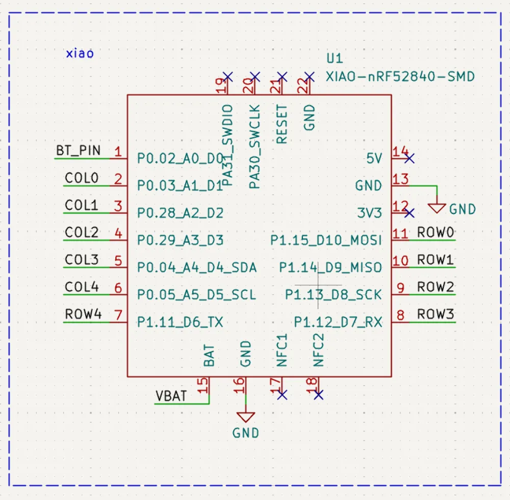
#Mounting points
#Add mounting holes
- In one of the hierarchical sheets, add 4-6 mounting points. I recommend you use M2-M3 screws.
#Mousebites
#Add three mousebite mounts to the root sheet
-
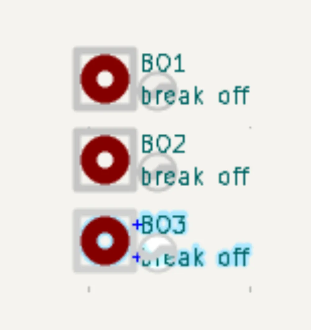
You should add three mounting points to the root sheet; we will assign mousebite footprints to these later on