The schematic is the circuit as an idea: which pin connects to what, and why. Everything you draw here becomes the PCB in the next page.
#Import the XIAO
-
Download the XIAO-ESP32-C3 symbol from the SeeedStudio Wiki - there's also an excellent video tutorial on using the board.

-
Press A (Add Symbol), search for the part, and place it:

-
Most symbols won't label every pin with its function (SDA, SCL, MOSI…) - they just show pin numbers. When that happens, google the MCU name + "pinout" and cross-reference which number maps to which function.
#Wire up power
-
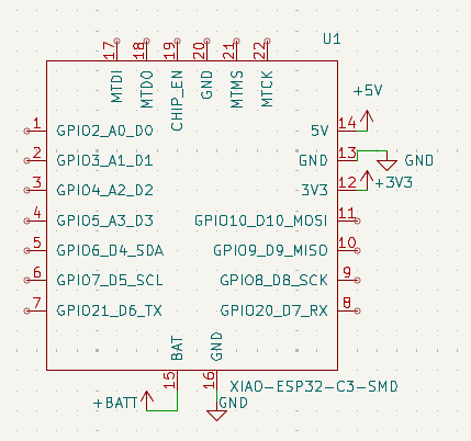
Connect GND to GND, 5V to +5V, +3V3 to 3V3, and BAT to +BATT:
-
Ground is the reference point for the entire circuit - the zero level everything else is measured against. Current flows from power, through components, back to ground; without it there's no return path and nothing works. If volts and rails are still fuzzy, read Voltage, Current & Resistance before continuing.
-
The XIAO exposes two rails: 5V comes from USB-C (on battery it gets nothing - a LiPo's ~3.7V can't supply it), while 3V3 is a stable 3.3V generated on-board, available on USB or battery. The OLED, sensors, and logic pins are rated for 3.3V, so they connect to 3V3 - too much voltage means too much current, which damages components.
Why not connect the top pads?
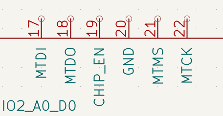
Those are JTAG debug pads - a special cable connects them to your computer so you can pause your program mid-run and inspect the chip line by line. USB-C handles everything this project needs, and wiring them would complicate the PCB for little benefit. Use them if you hit a bug Serial printing can't catch, or if you run out of GPIO pins.
#Add the OLED display
-
Import the 0.96" OLED from EasyEDA into KiCad - follow the easyeda2kicad guide.
-
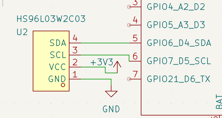
Connect GND to GND, SDA to SDA, and SCL to SCL with W. Those two data lines are I2C - one carries data, one carries the clock.
-
I2C normally needs Pull-up Resistors on both lines, but the XIAO includes internal pull-ups, so no external ones here.
-
The datasheet on the LCSC page says VCC wants 3V3, so:
#Add the buttons
-
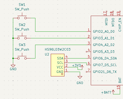
A Tamagotchi has three buttons. Wire each one active-low: one side to GND, the other to a GPIO pin with the XIAO's internal pull-up enabled.
-
"Active-low" means pressed = LOW (0V): idle, the pull-up holds the pin HIGH at 3.3V; pressing connects it to ground. It's the most common approach because it needs nothing but the button and a ground wire.
-
GPIO stands for General Purpose Input/Output - the programmable pins that read buttons or drive buzzers. On the XIAO, D0–D10 are GPIOs.
#Add the buzzer
-
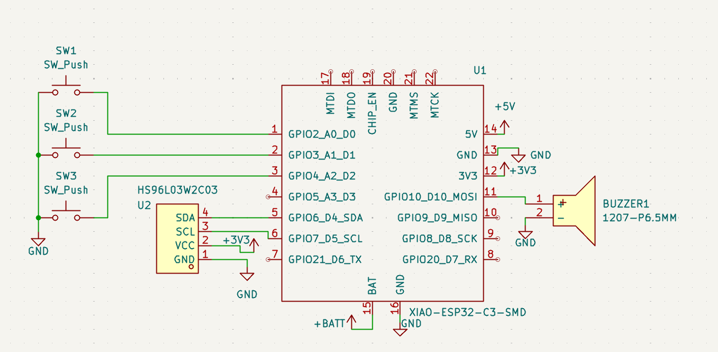
Add a buzzer (this one) - one pin to a GPIO output, the other to GND, so the GPIO can drive it with a square-wave tone.
#Power & battery
-
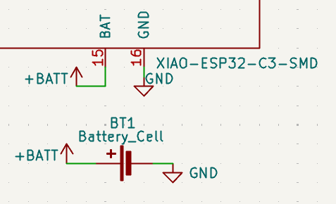
The XIAO has built-in battery charging: connect a LiPo directly to the BAT pin. The board runs wirelessly and recharges whenever USB-C is plugged in.
-
BAT connects only to the battery - it's a dedicated charging pin, separate from the 3.3V rail. GND is shared across everything; every component needs the common reference.
-
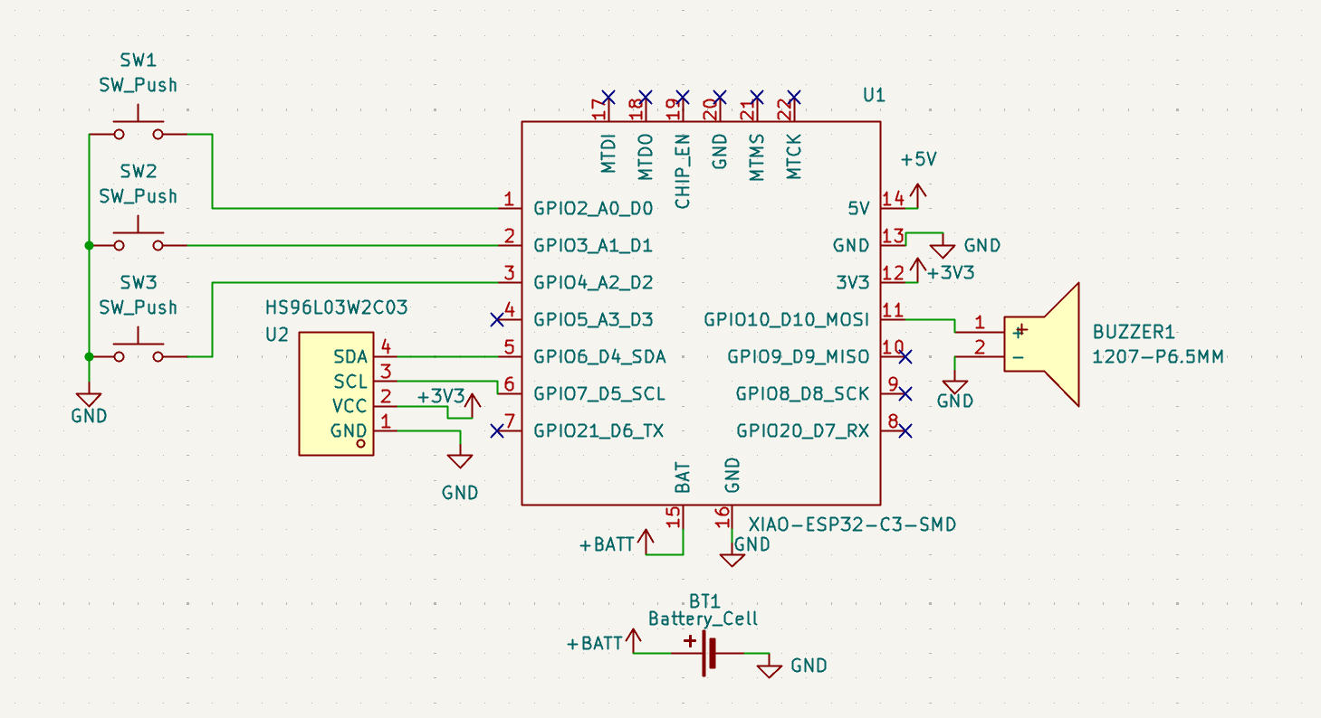
Place no-connect flags on every unused pin: press Q, then click the pin.
#Assign footprints
-
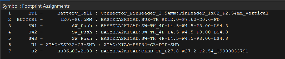
The schematic is done - now every symbol needs a physical footprint. Click this:
-
Battery connector: 2.54mm male headers - the standard pin spacing on most hobby electronics.
-
Buzzer: the AliExpress listing says 12 × 9.5mm (12mm diameter, 9.5mm pin spacing) - that's the
Buzzer_12x9.5RM7.6footprint. Careful: EasyEDA's buzzer footprint uses 7mm spacing instead of 9.5mm. -
Buttons: import from LCSC C2888493.
-
XIAO: the
XIAO-ESP32-C3-DIP-SMDfootprint from the official footprint library - we'll modify its SMD pads to through-hole later so the XIAO solders on directly. -
OLED: the EasyEDA import from earlier.