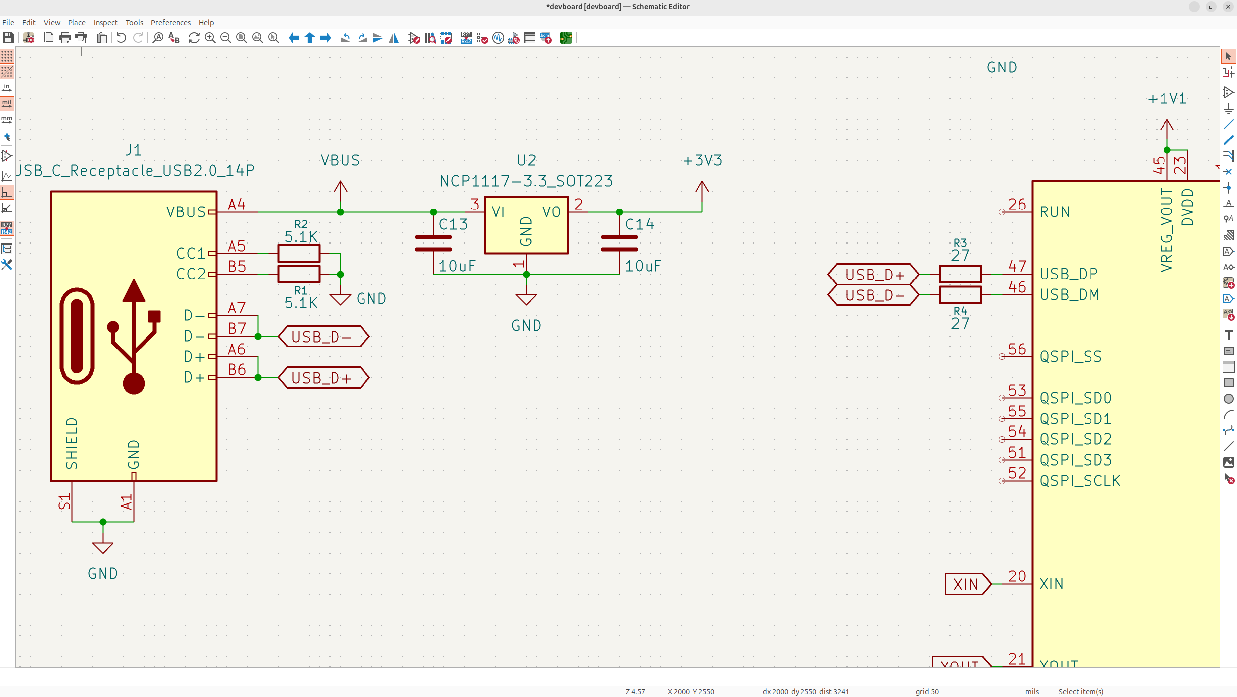
We have our power decoupling, but we don't actually have a power source yet or a way to program our devboard yet, so let's do that now. I'm going to be using USB-C because it's standard and fast!
#Add the USB-C receptacle
-
Tap "a", type in whatever receptacle you want, and add it in. Make sure you pick "receptacle" and not plug because a plug would plug into your laptop instead of having a cable plug into it.
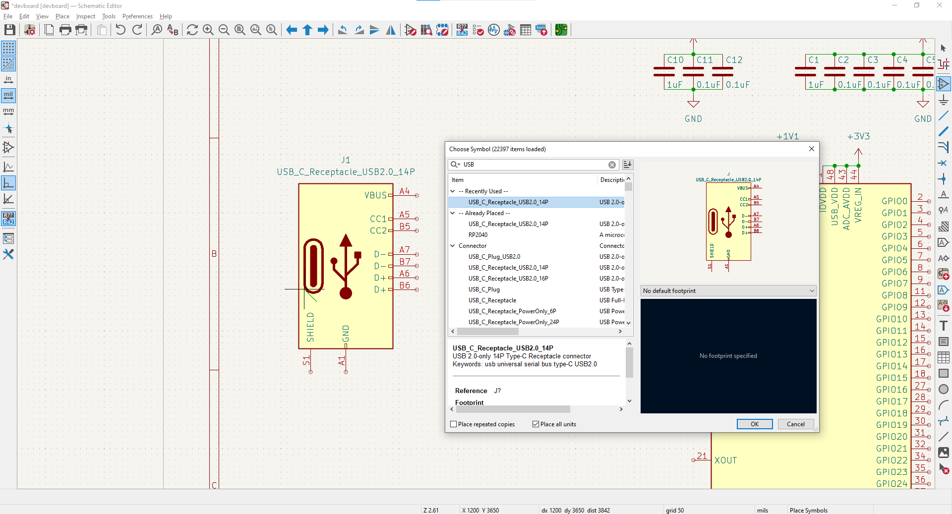
Now let's explain each of these pins:
- SHIELD/GND will both go to ground, shield is conductive material wrapped around the data pins on the receptacle, and this just improves EMI by grounding it.
- D+/D- are the data pins, these transfer data to/from the USB-C receptacle. You'll want to connect the D-'s and D+'s together so that they both transfer data.
- CC1 and CC2 basically tell the receptacle to allow power to go through to power the board. These by standard (the datasheet tells you) are pulled down (go to GND) through 5.1K resistors.
- VBUS is the 5V input, this will need to be stepped down to 3.3V to power our MCU (microcontroller).
#Ground shield/GND
-
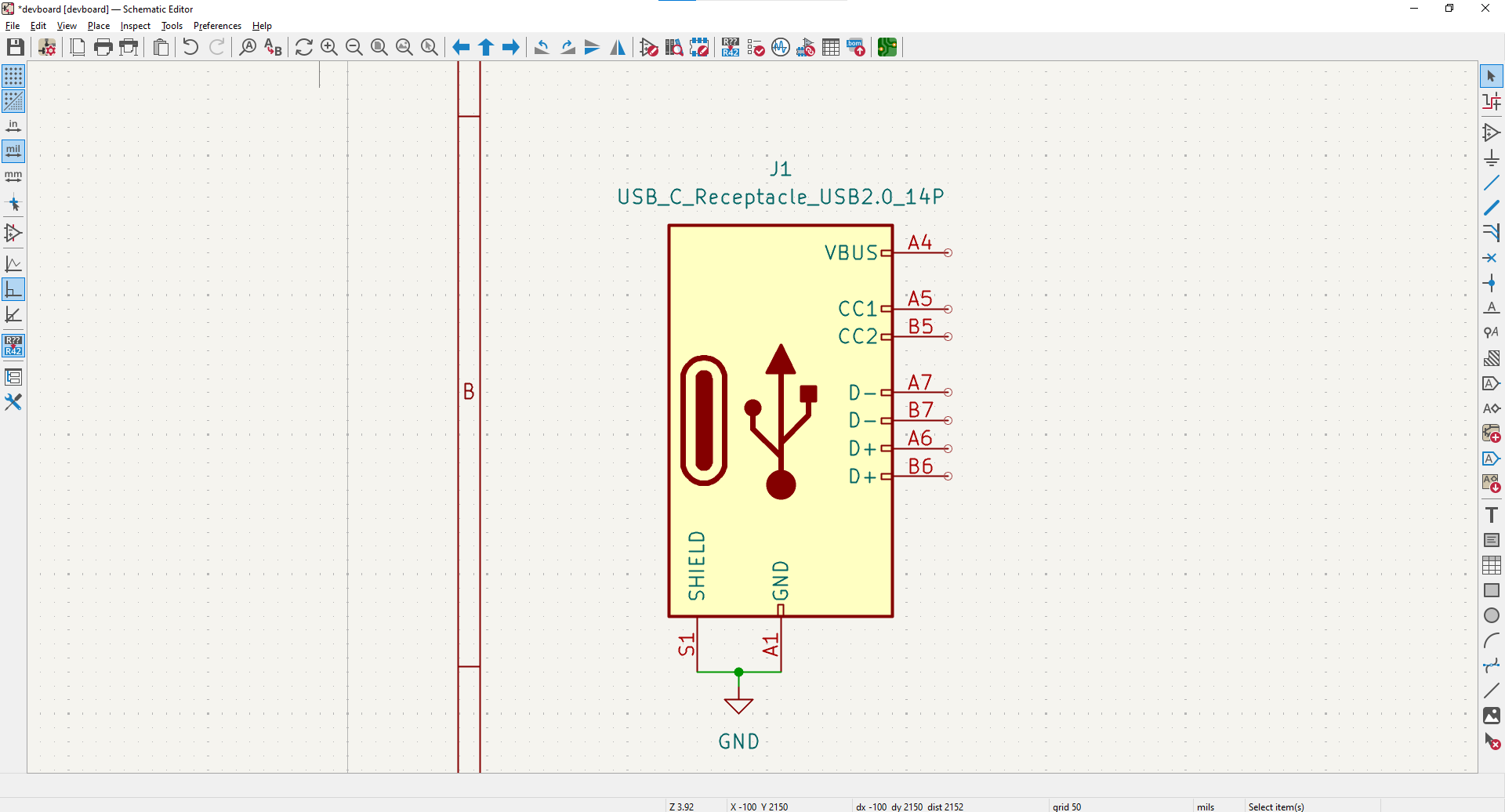
Now that we know what everything does, let's wire it up. Shield/GND go to GND:
#Label the data lines
-
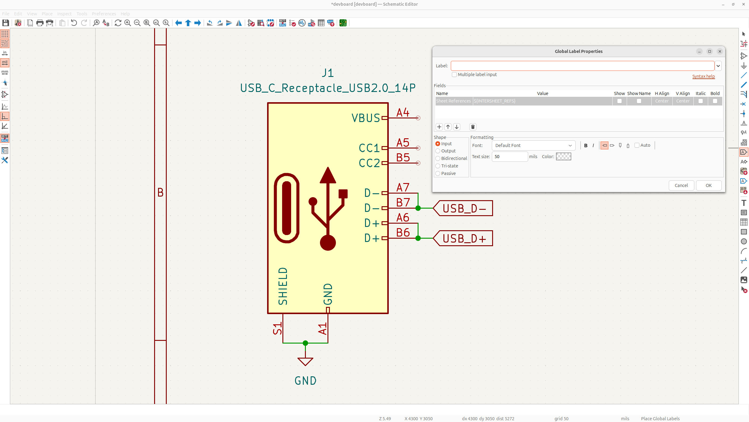
D+ and D- are attached to their relative pair, and then will go into the MCU, but for now, we'll just have a global label going out of them.
-
Global labels are basically like little teleporters, that allow you to say that something is wiring, without manually putting a wire between them. Technically global labels are meant to be used between different schematic sheets and net labels would be the correct thing to use here, but I find global labels are cleaner if you only have one schematic for your PCB.
-
Tap global label in the right hand toolbar, type in the name for your label (USB_D+ and USB_D-), and add them to the pins:
#Pull down the CC pins
-
Pulldown the CC pins through a 5.1K resistor to GND to enable power to go through the USB-C receptacle. Open up the symbol library, and then type "r" the shorthand for resistors, and then place it down and edit the value to be 5.1K:
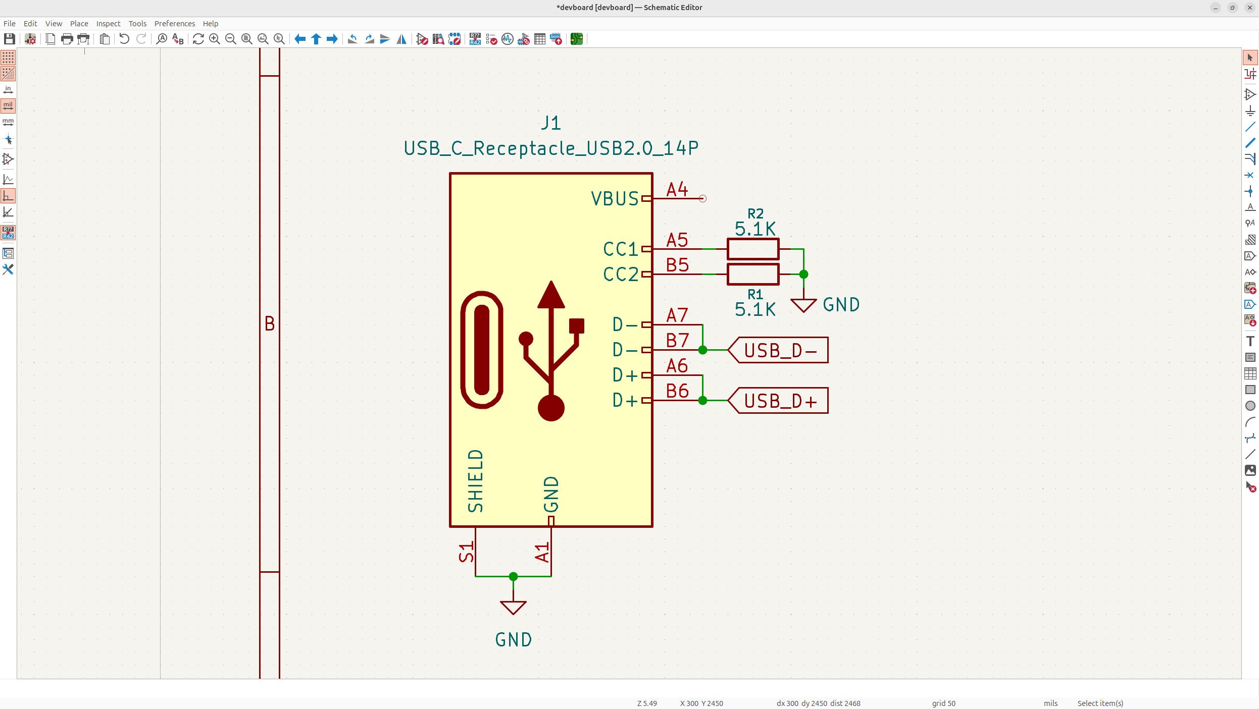
-
The CC pulldowns are one of the most common examples of pull resistors in the wild - here pulling the line down to GND to tell the receptacle to allow power through.
#The LDO
Now we just need to wire in the input voltage, but the thing is, the voltage of USB-C is 5V, while the voltage that the RP2040 uses as input, needs to be 3.3V so you don't cook it. To achieve this, we'll use what's called an LDO, or a Low-Dropout Regulator to take the voltage down.
Specifically, we'll be using the NCP1117, a classic and reliable fixed voltage regulator (I actually switch this regulator out later for the MCP1700, 3.3V, because it's really big on our PCB). A fixed voltage regulator is handy here, because we only need to go down to 3.3V instead of like 1.5V per say or something random, and it uses less components. We'll also be using the SOT-223 footprint (or package is the common term) because it's small and we don't really have any thermal issues with a devboard.
#Wire the LDO
-
Add in the NCP1117-3.3_SOT223 symbol, wire GND and attach VBUS to the VI (voltage input) of the LDO.
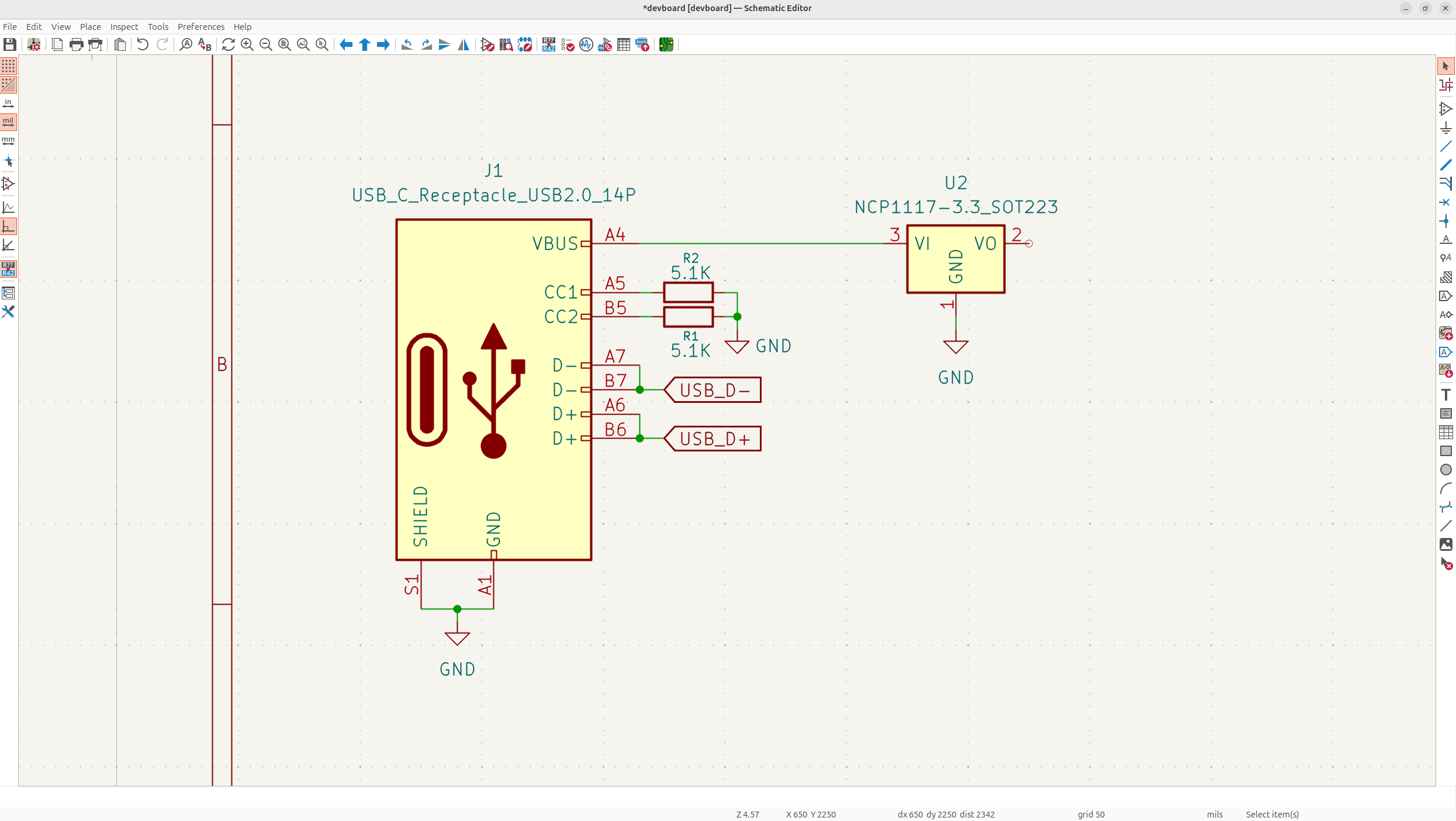
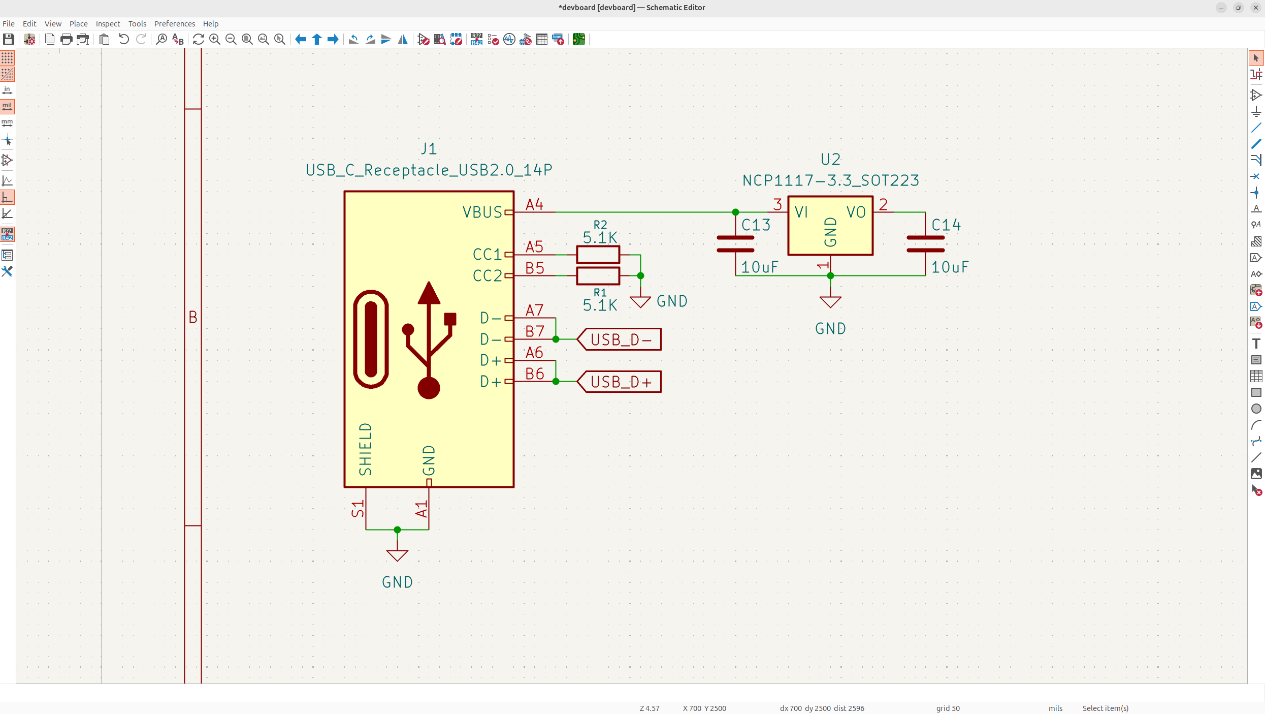
Remember to always keep your schematic clean and feel free to use up quite a bit of space. Now like the decoupling capacitors on our RP2040, we need capacitors on the LDO. But we don't need fine decoupling capacitors for precise input lines into an MCU, and instead we need bulk capacitors, to handle the large voltage ripples when moving a voltage down.
#Add the bulk caps
-
So we need to place two, 10uF capacitors on each side of the LDO, for input/output, so add them into your schematic:
#Label the power rails
-
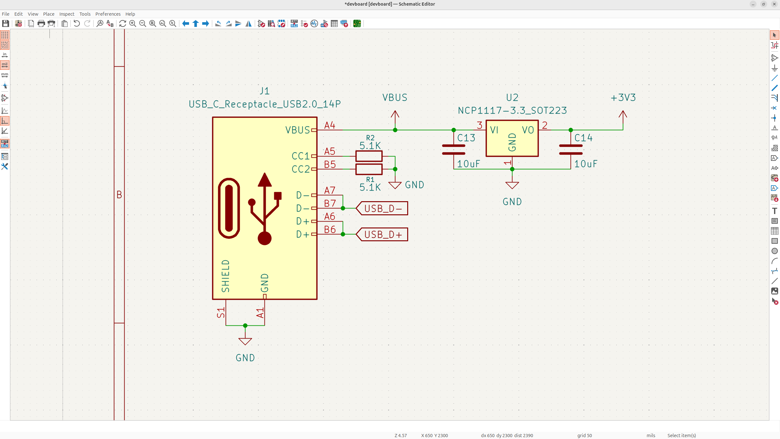
Next, we want to add our power labels to the LDO, we'll put a VBUS label before the LDO/Bulk cap, and a +3V3 label to the VO (voltage out) of the LDO. We might use 5V to power some other devices so we'll want to provide a power line for that too:
#Termination resistors
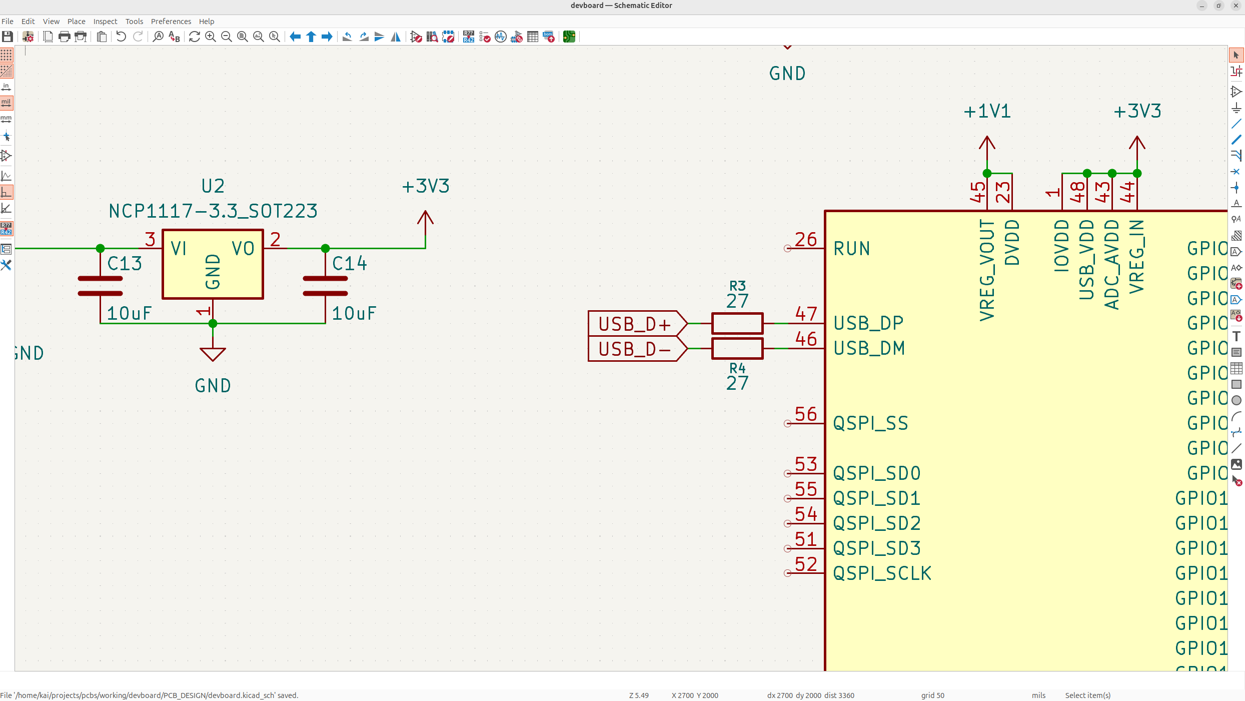
Now to finish off the USB-C wiring, we need to make sure the MCU receives the data lines. It's standard to have these going through 27 ohm resistors into the MCU to prevent distortions of the signals at high speeds, these are called termination resistors.
#Route the data pairs through the resistors
-
Wire the USB D+ and D- pairs into the MCU USB_DP and USB_DM (the P is for + and the M is for -) through 27 ohm resistors:
#Mark the data labels bidirectional
-
Now USB D+ and D- are actually what's called "bidirectional", this means that they work both ways. You don't actually need to specify this, but good schematic practices is to make sure your global labels reflect that.
-
Currently they're just set as "inputs" because the triangle is facing inwards, so double click on all the D+ and D- labels and set them to bidirectional: