
Before continuing on to the PCB, we have to Assign Footprints which
basically tells KiCad how big each component is physically and how the
connections look in real life to be able to solder it.
#Open the footprint assigner
-
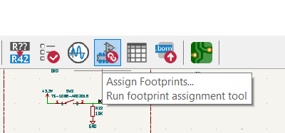
Click on this button to open the footprint selection screen:
-
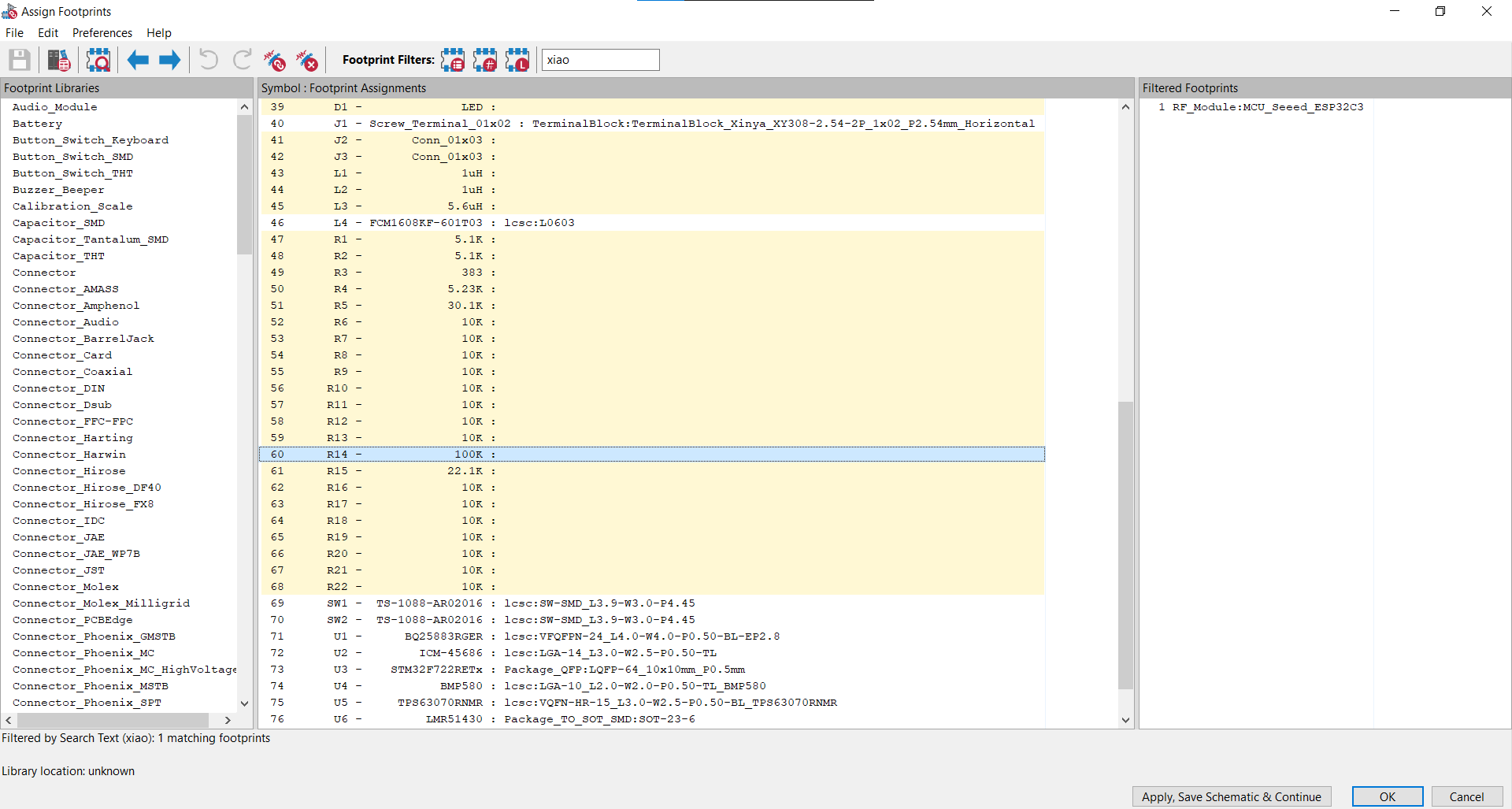
The lines in yellow are components whose footprints we have to assign:
-
But since it's mainly resistors and capacitors, that makes it a lot easier.
Since we're designing a flight controller, this has to be as small as
possible, so I am going to be choosing the smallest footprints I can
(while staying within good practices). The smaller the footprint, the
more it can heat up and the less it can tolerate (for resistors and
capacitors). A rule of thumb that I go by is any resistors under 80K I
assign a 0201 footprint, over that and it's 0402. For capacitors, any
bulk capacitors (capacitors that have high values like 4.7 µF or 10 µF)
I usually assign 0402. Any bigger than 10 µF and I assign 0805, but it
depends on the datasheet of the component. Under the application and
implementation section there is usually a table that specifies which
footprints/components to use.
Now all that's left is to finish adding the footprints for these symbols:

For the LED, I am going to have it in a 0402 package. And for the headers, I am going to use these footprints (basically the standard headers for jumper cables):

#Inductors
The inductors are a bit trickier. For this, you're gonna have to go into the datasheet and see where it says the size:
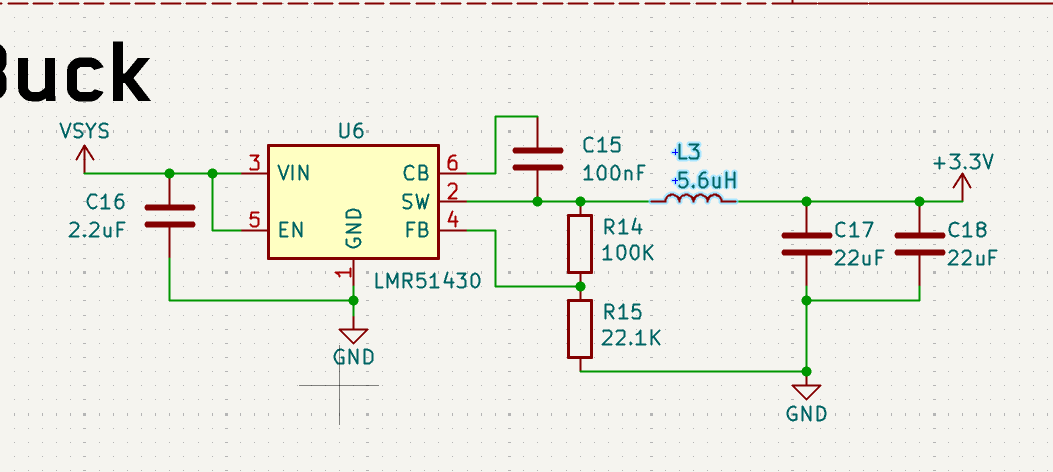
For that 5.6uH inductor, I am going to be using C18236327 (LCSC Part
Number).
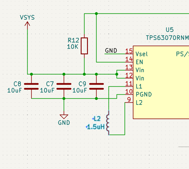
For the 5V buck-boost, I am going to be using C3033018. I also noticed
that I had the inductor value wrong from the datasheet. THIS IS WHY
DOUBLE CHECKING IS IMPORTANT:
For the final inductor in the battery charging IC, I am going to use
C435392.
#Save and re-import the new parts
- Press
Apply, Save Schematic & Continueto save the footprints you have already placed and then import the new inductors that you have selected.