Since we are using an STM32, there is a really cool piece of software called STM32CubeMX. It basically allows you to select the functions and types of communication that you need, and it automatically selects the pins so that we don't have to read the datasheet and get stuff wrong.
#Install STM32CubeMX
-
Download it here and wait for it to install.
-
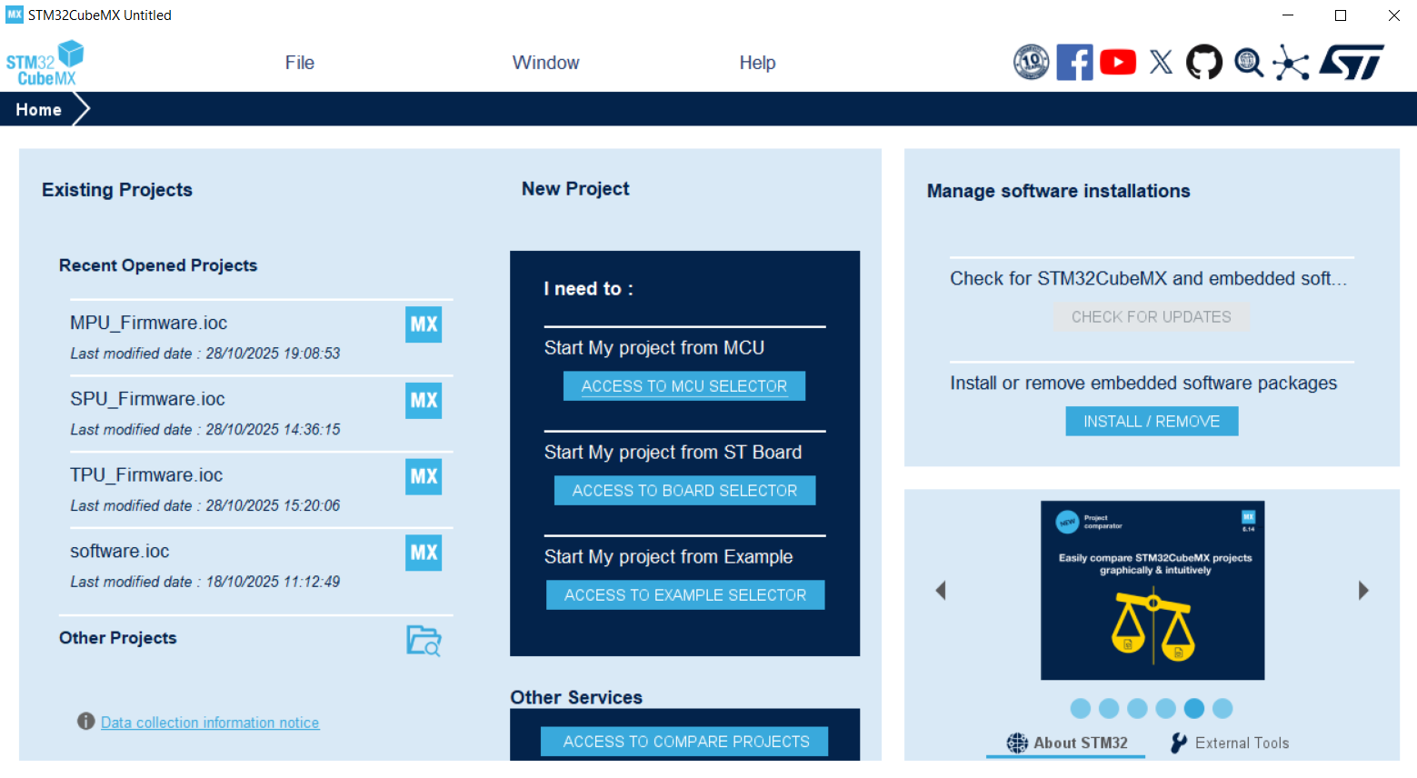
After installing it and opening it, you should be presented with this screen:
#Pick the STM32F722RET6
-
Click on
ACCESS TO MCU SELECTORas we are going to create a new project based on the MCU that we are using: in this case,STM32F722RET. -
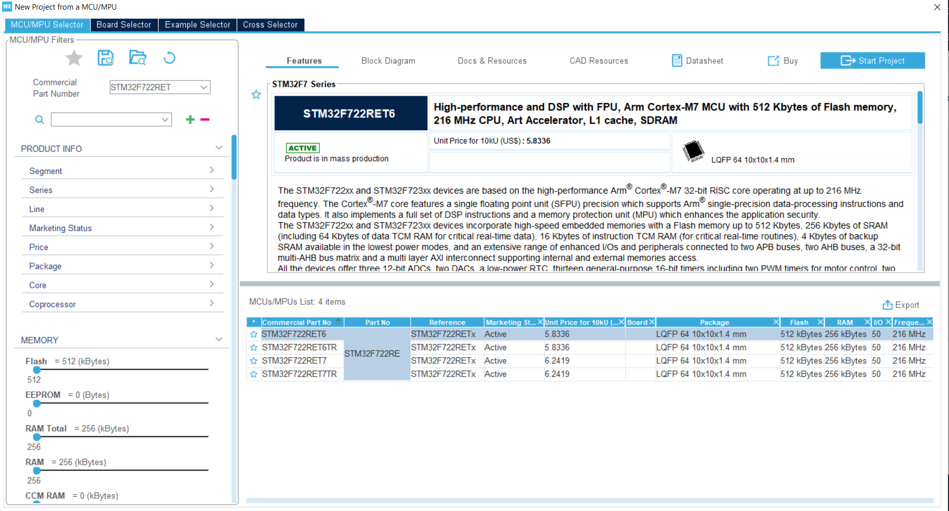
After searching for the MCU, you should see this screen:
-
Here, it shows different variations of that version for the STM32, but we are going to select the
STM32F722RET6version as it is the one that has the most in stock on LCSC.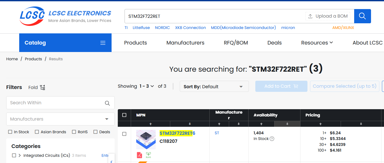
-
After that, hit "Start Project" at the top. If any windows pop up, say yes.
-
After loading/downloading the firmware, you should be greeted with this window:
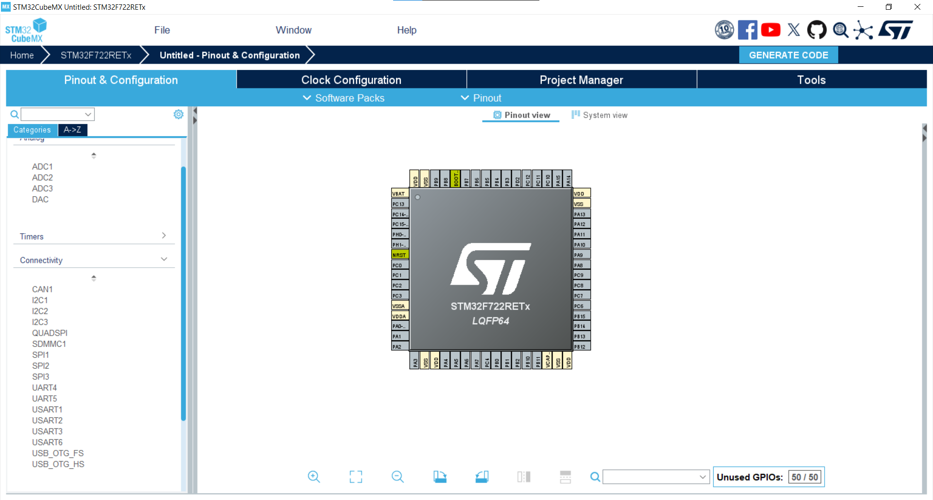
This is where you will be configuring the pinout for the STM32. On the
left, you can see the different sections that are able to be configured.
However, the only ones that concern us for now are the System Core,
Timers, and Connectivity sections.
#Connectivity
Here, we can see the different ways that we can connect the STM32 to
different peripherals through I2C, SPI, UART, SDMMC,
USB_OTG_FS, and more.
#Enable I2C for the charger + barometer
-
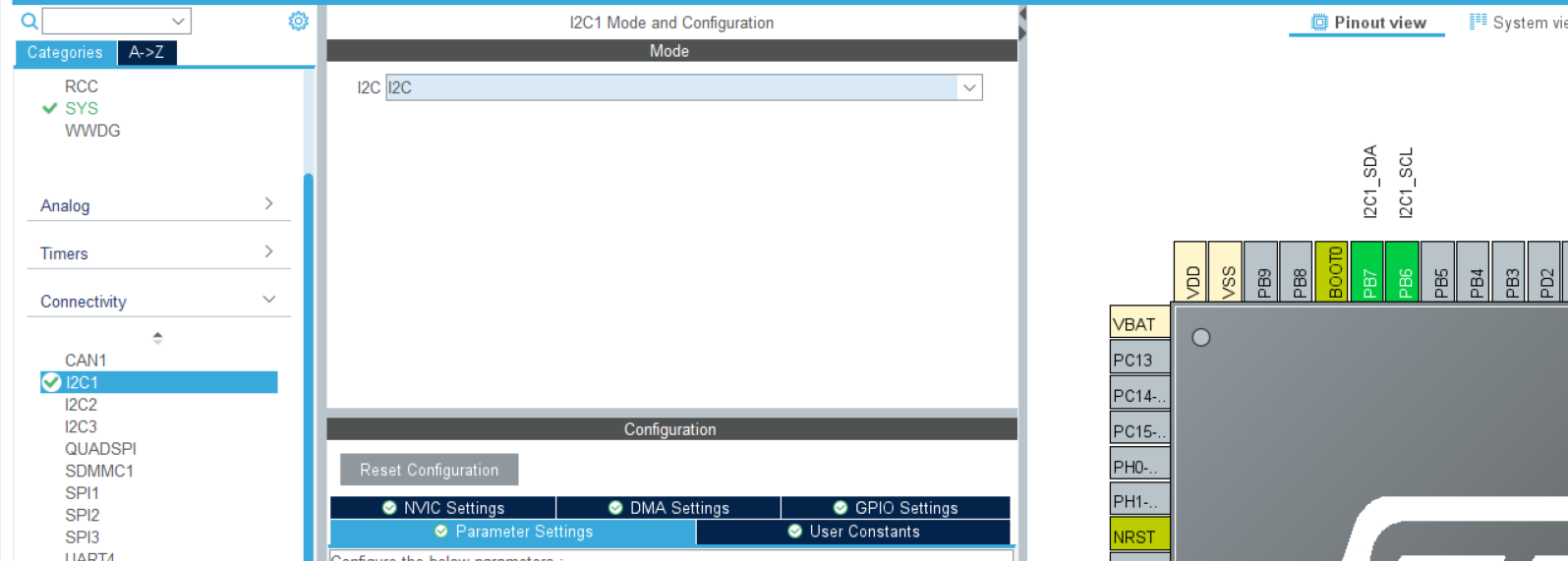
For now, enable the first I2C channel. This will be for the battery charger and pressure sensor. It should look like this:
-
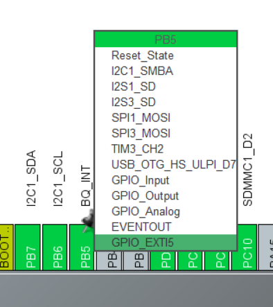
Also, be sure to select pins on either side for the battery charger interrupt and chip enable pins. The BQ_INT pin should be set as a GPIO_EXTIx (x is any number) pin as this lets the STM32 know that this pin is going to be an interrupt pin.
-
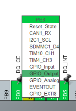
For BQ_CE, make sure that there's a pin set to GPIO_Output. According to the datasheet, when the pin is low, charging is on, and when it's high, the battery doesn't charge. We can change this later in the code for further customization in case you don't want the battery charge controller running during flight.
#Enable SPI for the IMU
-
Then enable an SPI channel for the IMU. You are free to use whichever channel you wish, but I am going to select the first one. Select
Full Duplex Masteras the STM32 will be the master and the IMU the slave, and full duplex because we are using both MOSI and MISO and not just one channel for input/output (half duplex/SDIO). -
There is also an option under the selection to activate a
Hardware NSS Signal. This is used if we have just one device under the SPI bus and makes it so that the STM32 manages theChip Selectpin instead of us having to select a GPIO for it. I enabled it asHardware NSS Signal Outputas the IMU will be the input. After selecting SPI, it should look like this (it can be different if you want to use a different pin for the Chip Select):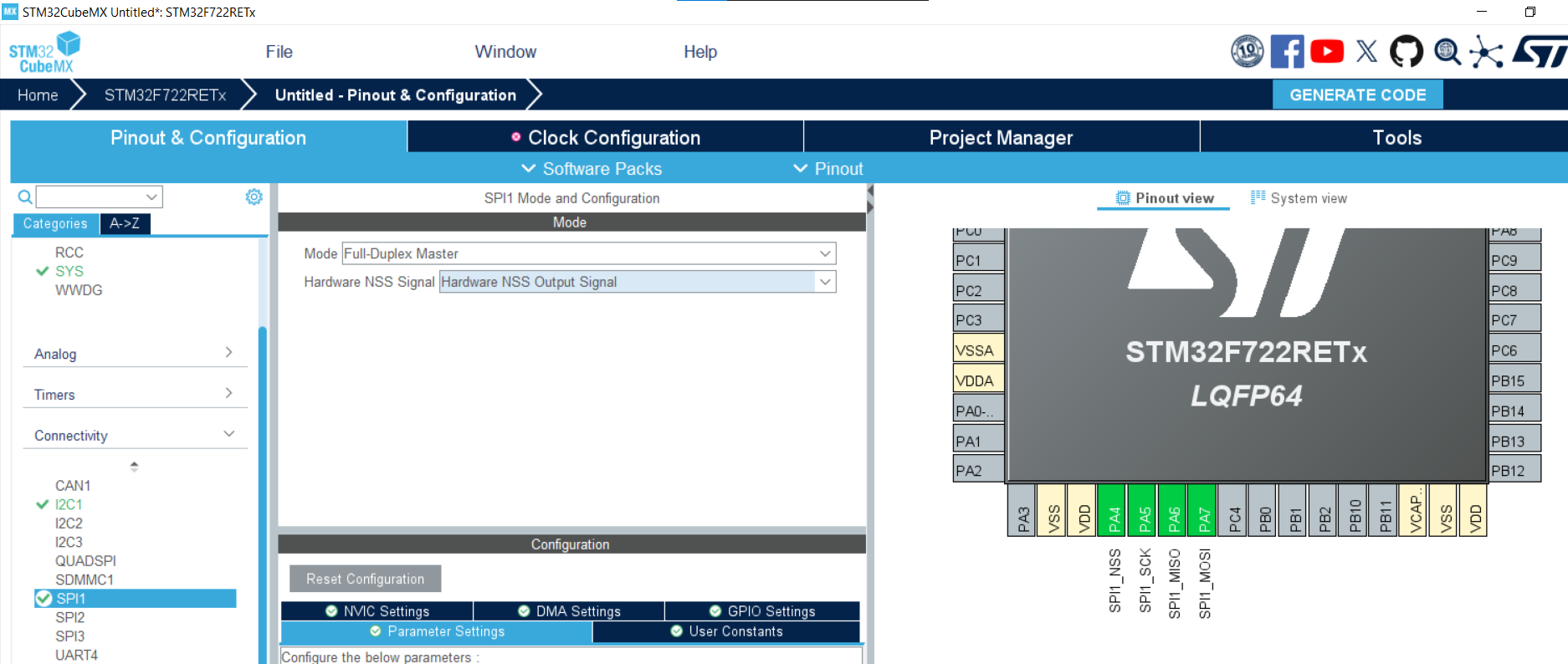
-
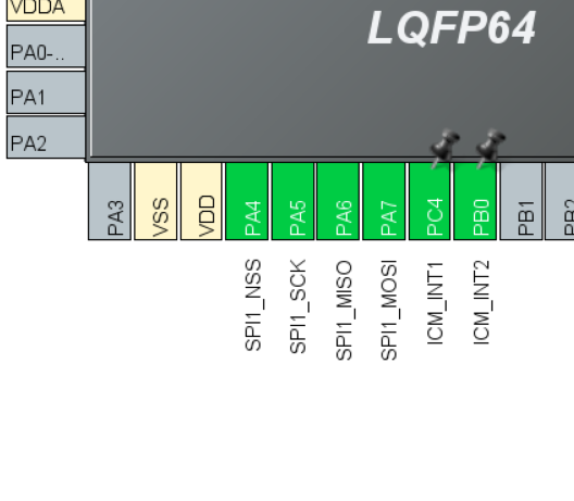
Also, don't forget to add the 2 interrupt pins on the IMU as GPIO_EXTIx (x is any number):
#Enable USB_OTG_FS
-
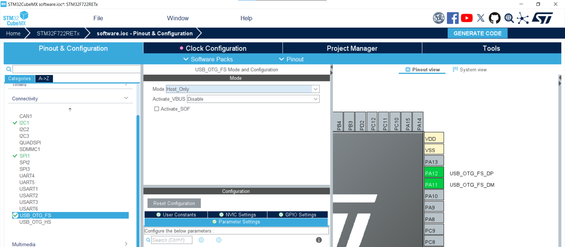
After you've done that, it's time to select
USB_OTG_FS. This means USB On-The-Go Full Speed, and it differs fromUSB_OTG_HS(USB On-The-Go High Speed) as it is slower and doesn't need any extra pins to configure. It's sufficient for our needs of flashing and sending serial data. -
Set it to host or device (you'll be changing this later depending on your needs). For now, I will leave it as host, and it shows where the USB pins are on the chip.
#Enable SDMMC (4-bit)
-
Now enable
SDMMCas this is the communication protocol that we will be using to write/read to our microSD. This should be enabled and set to a 4-bit bus.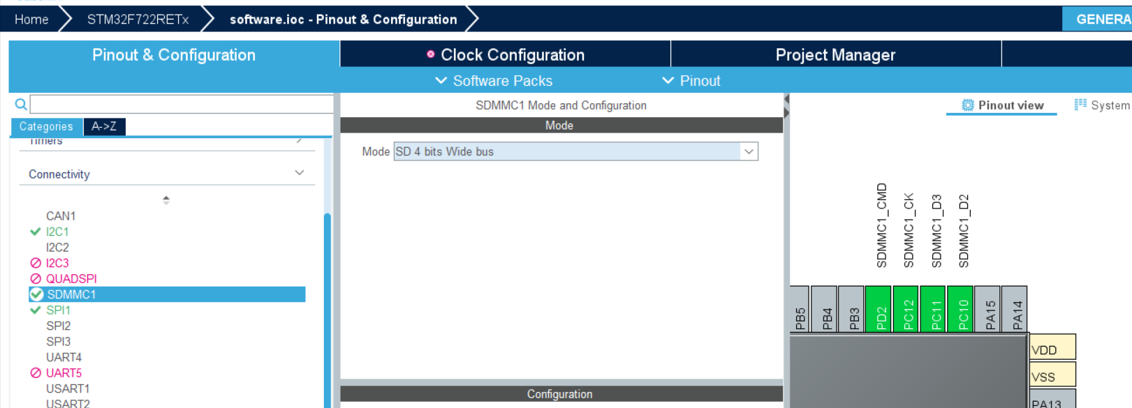
-
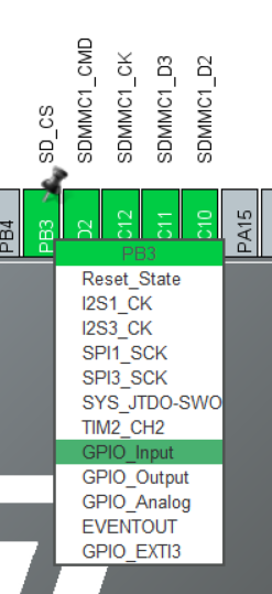
Also, remember to add an extra pin next to it for the card detect pin and make it a GPIO_Input:
#System core and timers
Now that we are done with our peripherals/sensors, we are going to configure some other stuff that would be important in starting the STM32 and configuring the servos.
#Enable external clocks in RCC
-
Go to the
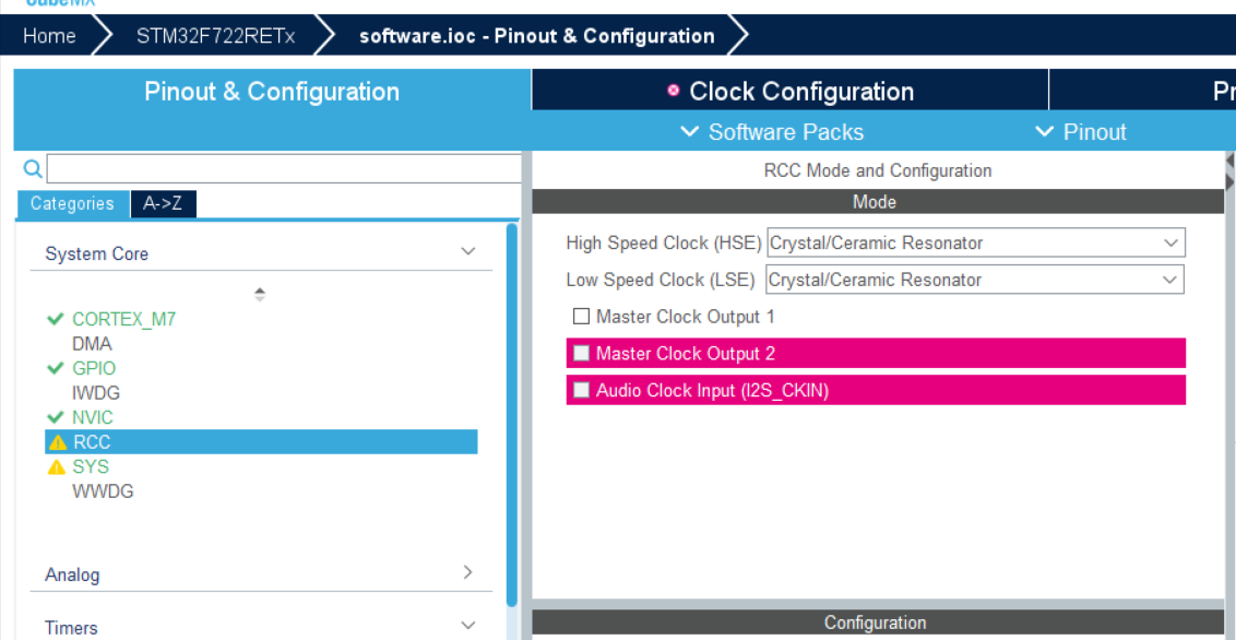
System Coretab, then click onRCC, and set both the high-speed clock and low-speed clock as a crystal/ceramic resonator. -
By doing this, we are telling the STM32 that we will have some external clocks that it can use to achieve faster/stable clock timing throughout the entire chip. We will edit this in KiCad later along with the pins.
#Set up PWM for the servos
-
Now go to the
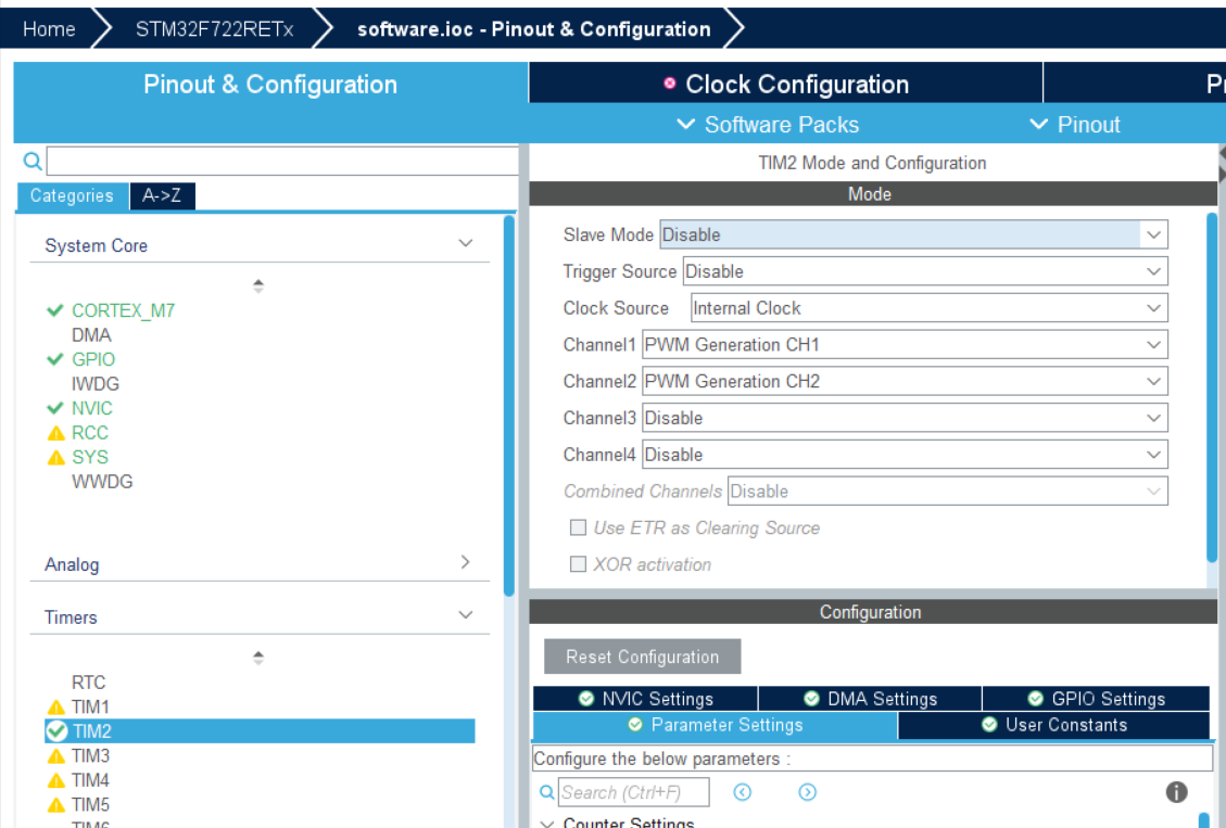
Timerssection. Here is where we can edit the PWM pins for the servos. Select any timer that has channels that support PWM and select 2PWM Generation CHchannels. We will be able to edit the duty cycle later in the firmware. -
Also edit the
Clock Sourceand set it to the internal clock. This is needed for the PWM generation as it needs a clock to time the signals correctly.