
Now that we've got power out of the way, it's time to route the sensors and the microSD.
#BMP580
Starting with the BMP580, when I try to open the datasheet, it says that no datasheet is defined. So you have to look it up on Google and found this.
Looking around the table of contents, there is no
Application and Implementation section, but there is a
Pinout and Connection Diagrams which is close enough:
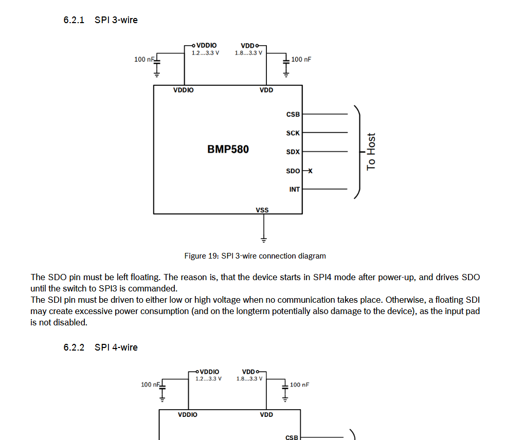
Taking a look at the different schematics, there are different ways of
connecting the chip through SPI, I2C, and I3C. Above in the
Communication Protocols section, I explained what each of these
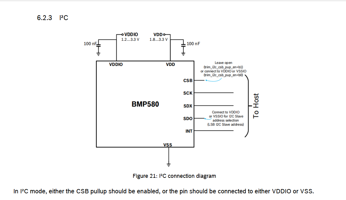
mean. For this chip, I plan on using I2C
as it's the default mode of communication for this chip. (This is
personal preference; feel free to use whichever mode of communication
you wish.)
When implementing I2C, you need to have pull-up resistors on each line.
However, if you recall, the battery charging circuit uses I2C as well,
and we already put pull-up resistors there, so it isn't necessary to add
them here. (See Pull-up Resistors if you want the
full why.)
#Wire the BMP580
-
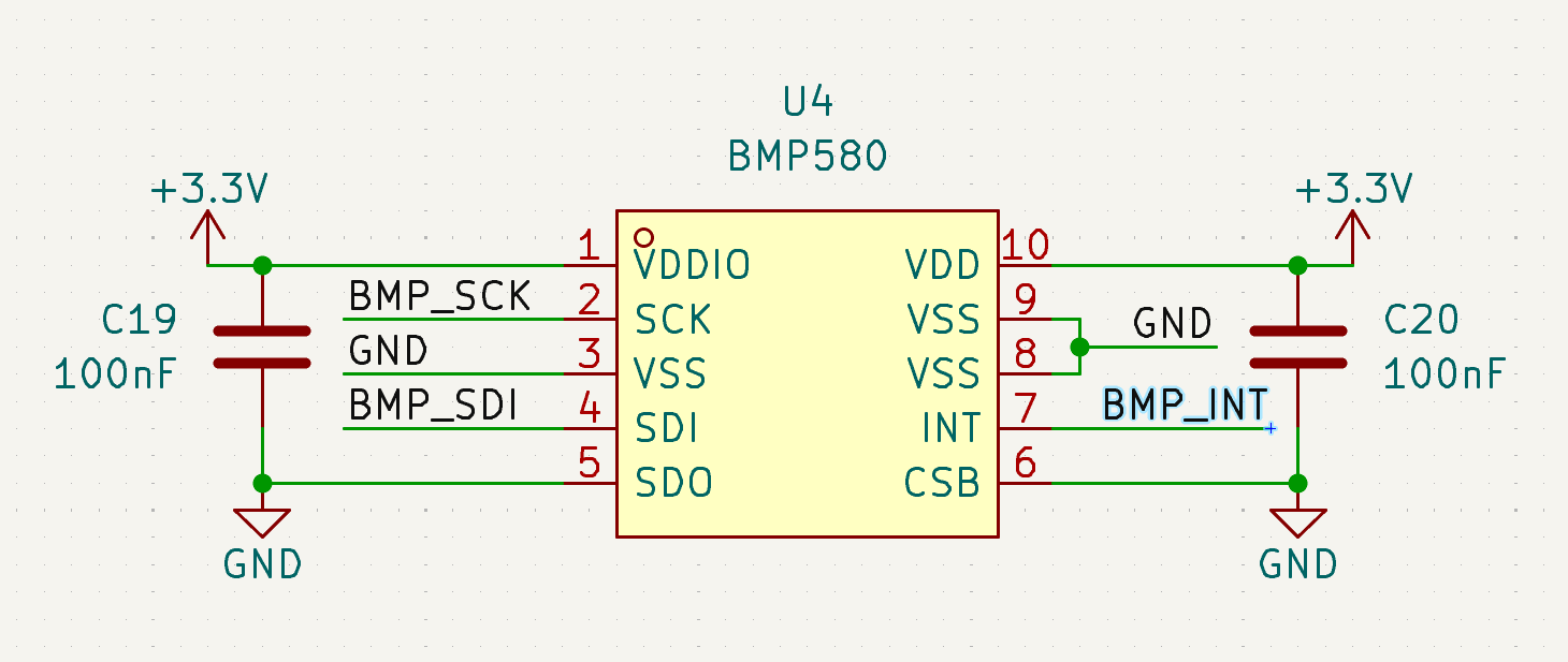
Following this schematic, after wiring it up in KiCad, you should get this:
-
I wired both VDD and VDDIO to 3.3V as that is the voltage that all of the other chips are running at (microcontroller and sensors).
#ICM-45686
Looking at the ICM-45686
datasheet,
it has different modes of operation like the BMP580. However, the one
that interests us is this one:
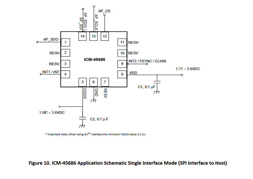
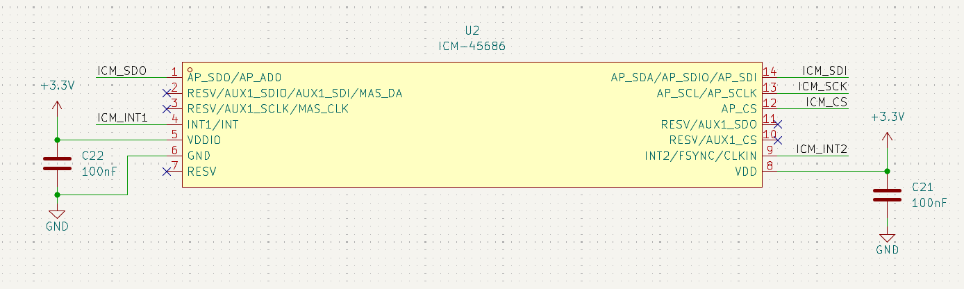
Changing things up a bit, we are going to connect the sensors to the microcontroller through SPI. This gives us the advantage of faster data and also allows us to learn how to implement it later on in code.
Also, in the schematic, looking at pin 14, it serves the dual purpose of being a SDIO or SDI. However, in our case, we want to use it as SDI to use the full capacity of SPI.
#Wire the ICM-45686
-
You should end up with something like this after:
#MicroSD card
MicroSD works on the same principle as SPI but can have more channels for faster data throughput. This form of communication is called SDIO (Secure Digital Input Output) and can work in 1-bit or 4-bit data modes (4-bit has more channels and faster data transfers).
Here is an example schematic of how the SD card should be wired, but we are going to modify it a bit to fit our needs. There are 8 pins on the microSD, and here's a table showing their meaning:
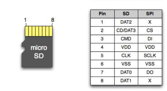
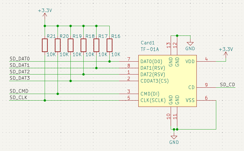
In SDIO (SDMMC) mode, DAT0-3 are used for data transfer, CLK for clock, and CMD for sending/receiving commands between the microcontroller and microSD card. DAT3 can also be considered a CD (Card Detect) pin, but usually, there is a 9th pin on most symbols that uses the case directly to detect if there is an SD card or not.
#Wire the microSD slot
-
After wiring it up, you should get something like this:
Now all that's left is to connect everything to the microcontroller!