
Before starting any engineering project, define the problem you're solving
and the constraints you have. Imagine you want to build a rocket. All
flight controllers include a microcontroller, which is a small computer
that can be programmed to do various tasks. To control the rocket's
flight, you'll use servos to move fins or a TVC system (Thrust Vector Control- tilting the engine nozzle to steer the rocket).
If you only build a board to drive servos, the rocket won't know which way it's pointing or how to correct its trajectory. You also need position and motion data (rotation and acceleration), plus altitude data. Finally, you'll want to store data persistently (even when powered off) for debugging and post-flight analysis.
Now that we have the rocket's functionality defined, we also need a way to power it. We can use a battery that can power both the rocket's computer and its servos.
Putting this together, we want these features in our rocket's flight controller:
- Can control servos for fins or TVC
- Can obtain position and altitude data
- Can store data even when powered off
- Can be powered by a battery
#Next steps
Now that we have our requirements, let's see how to meet them. Some requirements depend on others. For example, we want battery power - but how large should the battery be? That depends on the voltages and current the servos and microcontroller need, so let's define those first.
Depending on the size of your rocket, current needs will vary because larger servos draw more current. Most hobby servos run on 5-6V and draw ~1A. A 2-cell LiPo (Lithium Polymer) battery (7.4V nominal) is common in RC applications (each cell is ~3.7V) and can be regulated down to 5V for servos.
Most microcontrollers and sensors run on 3.3V, so with a 2-cell (7.4V) LiPo we have more than enough input voltage—as long as we regulate it down to a clean 3.3V line.
Now, after checking off one of the features, we need to tackle the three others.
- Can control servos for fins or TVC
- Can obtain position/altitude data
- Can store data even when powered off
Can be powered by a battery
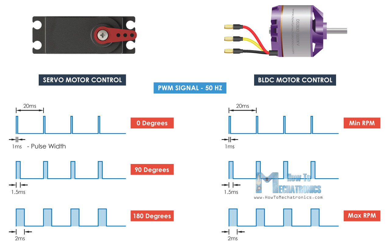
After choosing servos, we need to know how to control them. Most hobby
servos use PWM (Pulse Width Modulation)—a method of control where the
microcontroller sends rapid on/off pulses, and the pulse width (duration)
determines the servo's position.
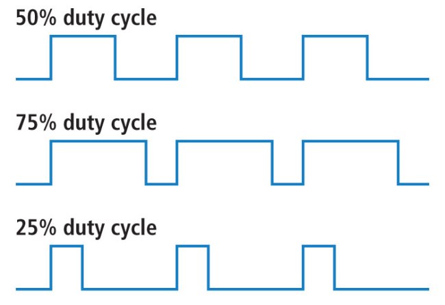
The duty cycle is the percentage of the period that the signal is high
(on).
#What about the sensors and microcontroller?
Needs to be able to control servos for fins or TVC- Needs a way to get position/altitude data
- Needs to store data even when the rocket is off
Needs to be able to be powered by a battery
For position and motion data, we use an IMU—an Inertial Measurement
Unit. The IMU measures acceleration and rotation (and some devices also
estimate altitude). We'll use the ICM-45686. While there are many IMUs
with different features, this one is robust and well-supported.
For altitude, we'll use a dedicated sensor called a barometer. It measures
air pressure and uses that to estimate altitude. We'll use the
BMP580—a versatile and common choice for flight controllers.
Finally, to store data, we'll use a microSD card. While you can use onboard flash, microSD is more versatile when you want to access flight logs directly from a computer.
Now that we've defined the sensors and peripherals, we need to select a microcontroller. In this tutorial, we'll use an STM32, but you can adapt it to another MCU like the ESP32 if you want Bluetooth/Wi-Fi support. I prefer STM32 because it's relatively easy to program and widely used in flight controllers. After reviewing STM32 options, we'll use the STM32F722RET6 for its high clock speed and lots of peripherals. Feel free to choose another package or part for larger designs.
Needs to be able to control servos for fins or TVCNeeds a way to get position/altitude dataNeeds to store data even when the rocket is offNeeds to be able to be powered by a battery
#Power management
We have two power sources: USB-C from your computer (5V) and a battery (about 7-8.4V for a 2-cell LiPo). You cannot just wire them together. They need circuitry to choose which one feeds the board and to set the right voltages. The microcontroller typically runs at 3.3V, so we must lower the voltage (from the battery or USB-C) before it reaches the MCU.
To change the voltages, we need to use a regulator. There are two common kinds of regulators you'll hear about:
LDO—Low Dropout regulator. It only turns higher voltage into a slightly lower one. Easy and quiet, but it wastes the excess as heat.Switching regulator—A more efficient regulator. It can:buck(turn higher voltage down),boost(push lower voltage up), orbuck-boost(keep the output steady even if the input goes above or below it).
What we'll do on this board:
- Make a 3.3V line (for the MCU and sensors) using a buck regulator.
- Make a 5V line (for servos or accessories) using a buck-boost regulator so it stays at 5V even as the battery voltage fluctuates.
- Get a battery charging IC (Integrated Circuit—a chip) that can charge a 2-cell battery from 5V.
Now that we've specified what functionality we need, we need to select the chips that provide it. I personally love to use ICs from Texas Instruments as they have good documentation and a huge selection of power management chips for everything related to USB.
#Find the battery charger
-
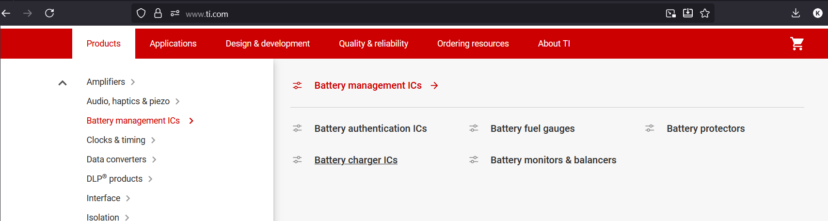
Go to their website (https://www.ti.com/), select "Products", then "Battery Management ICs", and finally "Battery Charging ICs". Here you can find all sorts of battery charging chips to fit your requirements for future projects.
-
After looking around a bit, I found the
BQ25883. It's a 2-cell Li-Ion/LiPo charger (which meets our requirement). You could add a more complicated battery charger if you want more cells/power, but they take up more space and are more complex to route.
#Find the regulators
-
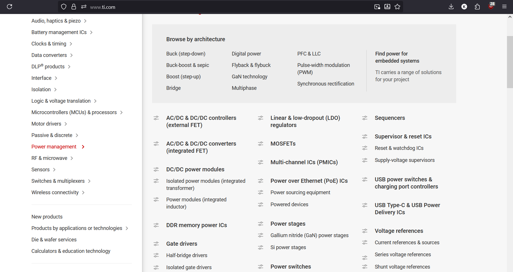
Go back to the TI main page, then navigate to "Power Management," then "DC/DC Power Modules." Here you can find all the regulators you would ever need, complete with excellent datasheets.
-
Here is where we can choose the right regulators for our needs. For this tutorial, we are going to use the
TPS63070, which supports 2-16V input and can output a steady 5V with high current for the servos. -
Now all that's missing is to find another regulator for 3.3V. For this, we are going to use the
LMR51430as it supplies a lot of amperage for the various sensors that we will be using.
Now that we have the chips that we are going to use, we also need to verify that they are available on some platform like LCSC or wherever else you are going to manufacture your PCB. We also might have to import certain components from LCSC into KiCad.
#Final component list
- USB-C
- MicroSD
- TPS63070
- LMR51430
- BQ25883
- STM32F722RETx
- ICM-45686
- BMP580
- Optional LED