
Now after finishing the battery charger, I am going to start wiring up
the regulators, starting with the TPS63070.
#TPS63070 (5V buck-boost)
Apply the same methodology as wiring up the battery charger: look up the
datasheet, go to the Application and Implementation section, and look
at the schematic. In this case, there are 2 schematics:
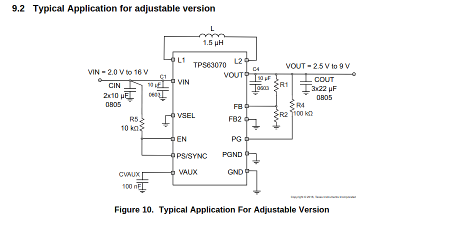 A typical application that can be adjusted depending on your needs.
And if you scroll down a bit more:
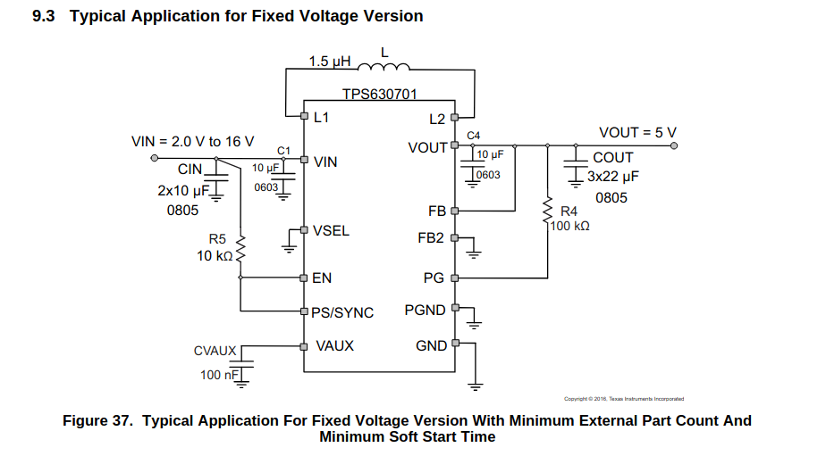 Another typical application, but this time it outputs a fixed voltage.
Really, the only difference is that for the adjustable version, there's a
voltage divider—a pair of resistors that can be used to create a
voltage less than or equal to the input voltage:
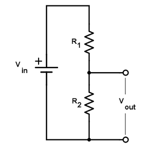
In the fixed version, we don't use a voltage divider so it stays at 5V (it's predetermined in the chip).
In our case, we are going to use the fixed version as it uses fewer components and also gives us the 5V that we need.
#Wire the TPS63070 in KiCad
-
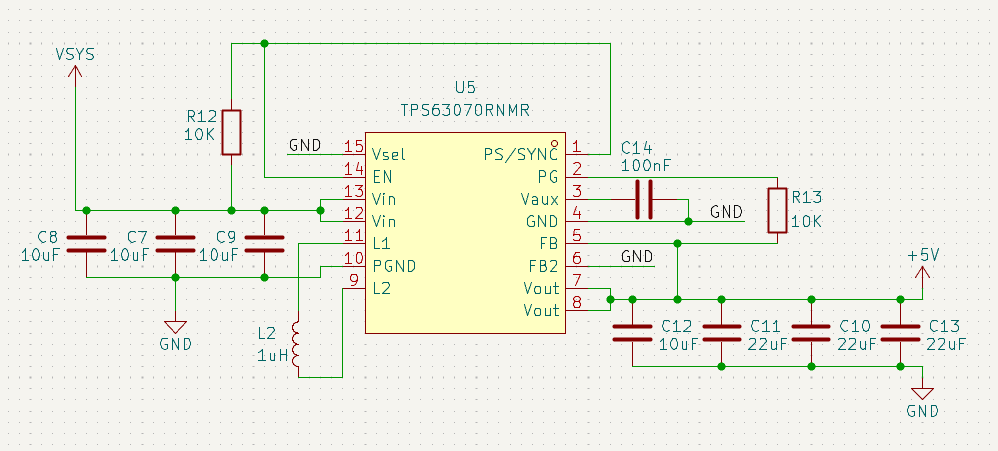
Using the fixed schematic (and taking into account the correct footprint sizes), wire it up in KiCad. You should get something like this:
-
With VIN connecting to VSYS (battery or USB voltage) and VOUT connecting to +5V. Separate grounds are not needed here, so they are GND.
-
If you don't know what footprint size to add to the other components (resistors, inductors, etc.), don't worry. We will revise this later.
#LMR51430 (3.3V buck)
Now moving on to the final power part, the LMR51430.
Repeat the same as the other 2 parts: open the datasheet and look for the
Application and Implementation section. Switching regulators (like the
name implies) switch MOSFETs (tiny gates) open and close very fast in
order to regulate voltage. This can be measured by the
switching frequency of the chip. In this case, we have 2 tables under
the schematic.
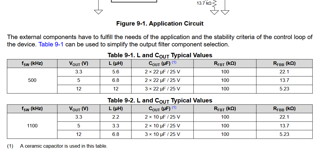
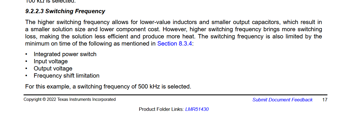
One for a switching frequency of 500 kHz and another one for 1.1 MHz (1100 kHz). With a higher switching frequency, it is less efficient and also can produce more heat. However, overall, the space it takes up is less than with the lower frequency. On the other hand, a lower switching frequency is more stable/efficient and doesn't heat up as fast. It also produces a lot less noise (which is what we need). So in this case, we will go with the lower switching frequency at 3.3V. If you want to wire it up based on the higher frequency, then feel free to do so. Just take into account the pros and cons of each one. (All of this information is from the datasheet, by the way.)
#Wire the LMR51430
-
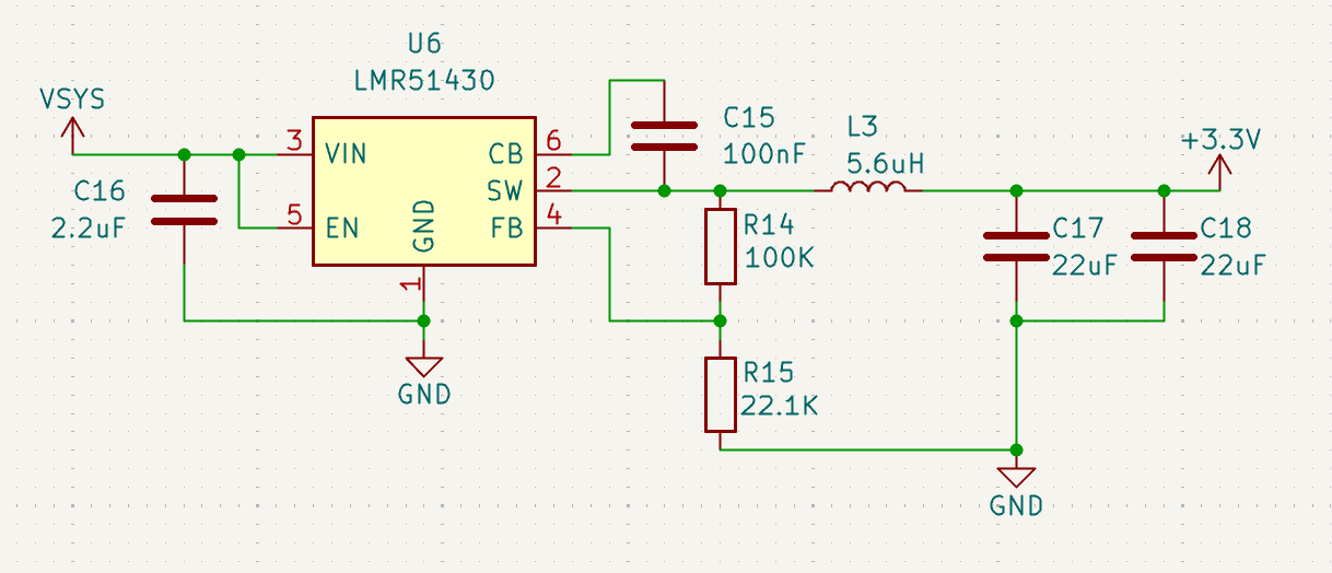
After routing it, you should get something like this (for a 500 kHz switching frequency at 3.3V):
-
Like the 5V regulator, VIN = VSYS, but VOUT = +3.3V as this chip is giving us 3.3V output.
-
Double-check the values on the resistor divider as that is what determines the output voltage. Also, in the reference schematic, it shows one capacitor of 44 µF, but in the table, it's 2 capacitors of 22 µF, so I used those.